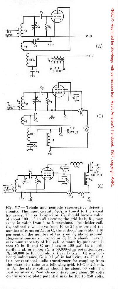
By providing controllable r.f. feedback (regeneration) in a tetrode or pentode detector circuit, the incoming signal can be amplified many times, thereby greatly increasing the sensitivity of the detector. Regeneration also increases the effective Q of the circuit and thus the selectivity. The grid-leak type of detector is most suitable for the purpose.
The grid-leak detector is a combination diode rectifier and audio-frequency amplifier. In the circuits of Fig. 5-7, the grid corresponds to the diode plate and the rectifying action is exactly the same as in a diode. The d.c. voltage from rectified-current flow through the grid leak, R1, biases the grid negatively, and the audio-frequency variations in voltage across R1 are amplified through the tube as in a normal a.f. amplifier. In the plate circuit, T1, L4 and L3 are the plate load resistances, C4 is a by-pass capacitor and RFC an r.f. choke to eliminate r.f. in the output circuit.
A grid-leak detector has considerably greater sensitivity than a diode. The sensitivity is further increased by using a screen-grid tube instead of a triode, as at 5-7 B and C . The operation is equivalent to that of the triode circuit. The screen bypass capacitor, C5, should have low reactance for both radio and audio frequencies. R2 and R3 constitute a voltage divider on the plate supply to furnish the proper screen voltage. In both circuits, C2 must have low r.f. reactance and high a.f. reactance compared to the resistance of R1. Although the regenerative grid-leak detector is more sensitive than any other type, its many disadvantages commend it for use only in the simplest receivers. The linearity is rather poor, and the signal-handling capability can be improved by reducing R1 to 0.1 megohm, but the sensitivity will be decreased. The degree of antenna coupling is often critical.
The circuits of Fig. 5-7 are regenerative, the feedback being obtained by feeding some signal to the grid back from the plate. The amount of regeneration must be controllable, because maximum regenerative amplification is secured at the critical point where the circuit is just about to oscillate. The critical point in turn depends upon circuit conditions, which may vary with the frequency to which the detector is tuned. In an oscillating condition, a regenerative detector can be detuned slightly from an incoming c.w. signal to give autodyne reception.
The circuit of Fig. 5-7A uses a variable bypass capacitor, C4, in the plate circuit to control regeneration. When the capacity is small the tube does not regenerate, but as it increases toward maximum its reactance becomes smaller until there is sufficient feedback to cause oscillation. If L2 and L3 are wound end-to-end in the same direction, the plate connection is to the outside of the plate or "tickler" coil, L3, when grid connection is to the outside of L2.
The circuit of Fig. 5-7B is for a pentode tube, regeneration being controlled by adjustment of the screen-grid voltage. The tickler, L3, is in the plate circuit. The portion of the control resistor between the rotating contact and ground is bypassed by a large capacitor (0.5 uF or more) to filter out scratching noise when the arm is rotated. The feedback is adjusted by varying the number of turns on L3 or the coupling between L2 and L3, until the tube just goes into oscillation at the screen potential of approximately 30 volts.
Circuit C is identical with B in principle of operation. Since the screen and plate are in parallel for r.f. in this circuit, only a small amount of "tickler" - that is, relatively few turns between the cathode tap and ground - is required for oscillation.
Smooth Regeneration ControlThe ideal regeneration control would permit the detector to go into and out of oscillation smoothly, would have no effect on the frequency of oscillation, and would give the same value of regeneration regardless of frequency and the loading on the circuit. In practice, the effects of loading, particularly the loading that occurs when the detector circuit is coupled to an antenna, are difficult to overcome. Likewise, the regeneration is usually affected by the frequency to which the grid circuit is tuned.
In all circuits it is best to wind the tickler at the ground or cathode end of the grid coil, and to use as few turns on the tickler as will allow the detector to oscillate easily over the whole tuning range at the plate (and screen, if a pentode) voltage that gives maximum sensitivity. Should the tube break into oscillation suddenly as the regeneration control is advanced, making a click, it usually indicates that the coupling to the antenna (or r.f. amplifier) is too tight. The wrong value of grid leak plus too-high plate and screen voltage are also frequent causes of lack of smoothness in going into oscillation.
Antenna CouplingIf the detector is coupled to an antenna, slight changes in the antenna (as when the wire swings in a breeze) affect the frequency of the oscillations generated, and thereby the beat frequency when code signals are being received. The tighter the antenna coupling is made, the greater will be the feedback required or the higher will be the voltage necessary to make the detector oscillate. The antenna coupling should be the maximum that will allow the detector to go into oscillation smoothly with the correct voltages on the tube. If capacity coupling to the grid end of the coil is used, generally only a very small amount of capacity will be needed to couple to the antenna. Increasing the capacity increases the coupling.
At frequencies where the antenna system is resonant the absorption of energy from the oscillating detector circuit will be greater, with the consequence that more regeneration is needed. In extreme cases it may not be possible to make the detector oscillate with normal voltages. The remedy for these "dead spots" is to loosen the antenna coupling to a point that permits normal oscillation and smooth regeneration control.
Body CapacityA regenerative detector occasionally shows a tendency to change frequency slightly as the hand is moved near the dial. This condition (body capacity) can be corrected by better shielding, and sometimes by r.f. filtering on the phone leads. A good, short ground connection and loosening the coupling to the antenna will help.
HumHum at the power supply frequency, even when using battery plate supply, may result from the use of a.c. on the tube heater. Effects of this type normally are troublesome only when the circuit of Fig. 5-7C is used, and then only at 14 Mc. and higher. Connecting one side of the heater supply to ground, or grounding the center-tap of the heater- transformer winding, will reduce the hum. The heater wiring should be kept as far as possible from the r.f. circuits.
House wiring, if of the "open" type, may cause hum if the detector tube, grid lead, and grid condenser and leak are not shielded. This type of hum is easily recognizable because of its rather high pitch.
(The following paragraph copied from 1950 Handbook)
Antenna resonance effects frequently cause a hum of the same nature as taht just described which is most intense at the various resonance points, and hence varies with tuning. For this reason it is called "tunable hum." It is prone to occur with a rectified a.c. plate supply, when the receiver is put "above ground" by the antenna, as described in a preceding paragraph. The effect is associated with the nonlinearity of the rectifier tube in the plate supply. Elimination of antenna resonance effects as described and by-passing the rectifier plates to cathode (using by-pass condensers of the order of 0.001 uF) usually will cure it.
TuningFor c.w. reception, the regeneration control is advanced until the detector breaks into a "hiss," which indicates that the detector is oscillating. Further advancing the regeneration control after the detector starts oscillating will result in a slight decrease in the strength of the hiss, indicating that the sensitivity of the detector is decreasing.
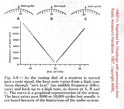
The proper adjustment of the regeneration control for best reception of code signals is where the detector just starts to oscillate. Then code signals can be tuned in and will give a tone with each signal depending on the setting of the tuning control. As the receiver is tuned through a signal the tone first will be heard as a very high pitch, then will go down through "zero beat" and rise agian on the other side, finally disappearing at a very high pitch. This behavior is shown in Fig. 5-8. A low-pitched beat-note cannot be obtained from a strong signal because the detector "pulls in" or "blocks"; that is, the signal forces the detector to oscillate at the signal frequency, even though the circuit may not be tuned exactly to the signal. This phenomenon, is also called "locking in"; the more stable of the two frequencies assumes control over the other. It usually can be corrected by advancing the regeneration control until the beat-note is heard again, or by reducing the input signal.
The point just after the detector starts oscillating is the most sensitive condition for code reception. Further advancing the regeneration control makes the receiver less susceptible to blocking by strong signals, but also less sensitive to weak signals.
If the detector is in the oscillating condition and a phone signal (AM) is tuned in, a steady audible beat-note will result. While it is possible to listen to phone if the receiver can be tuned to exact zero-beat, it is more satisfactory to reduce the regeneration to the point just before the receiver goes into oscillation. This is also the most sensitive operating point.
Single-side-band phone signals can be received with a regenerative detector by advancing the regeneration control to the point used for code reception and tuning carefully across the s.s.b. signal. The tuning will be very critical, however, and the operator must be prepared to just "creep" across the signal. A strong signal will pull the detector and make reception impossible, so either the regeneration must be advanced far enough to prevent this condition, or the signal must be reduced by using loose antenna coupling.