The frequency of a crystal-controlled oscillator is held constant to a high degree of accuracy by the use of a quartz crystal. The frequency depends almost entirely on the dimensions of the crystal (essentially its thickness); other circuit values have comparatively negligible effect. However, the power obtainable is limited by the heat the crystal will stand without fracturing. The amount of heating is dependent upon the r.f. crystal current which, in turn, is a function of the amount of feedback required to provide proper excitation. Crystal heating short of the danger point results in frequency drift to an extent depending upon the way the crystal is cut. Excitation should always be adjusted to the minimum necessary for proper operation.
Crystal-Oscillator Circuits
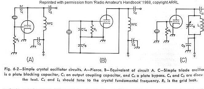
The simplest crystal-oscillator circuit is shown in Fig. 6-2A. An equivalent circuit is shown in Fig. 6-2B., where C4 represents the grid -cathode capacitance and C5 indicates the plate-cathode, or output capacitance. The ratio of these capacitors controls the excitation for the oscillator, and good practice generally requires that both of these capacitances be augmented by external capacitors, to provide better control of the excitation.
The circuit shown in Fig. 6-2C is the equivalent of the tuned-grid tuned-plate circuit discussed in the chapter on vacuum-tube principles, the crystal replacing the tuned grid circuit.
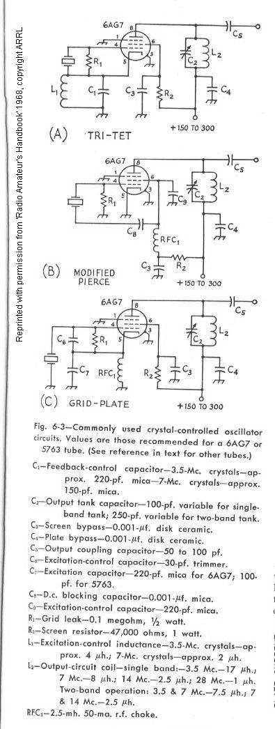
The most commonly used crystal-oscillator circuits are based on one or the other of these two simple types, and are shown in Fig. 6-3. Although these circuits are somewhat more complicated, they combine the functions of oscillator and amplifier or frequency multiplier in a single tube. In all of these circuits, the screen of the tetrode or pentode is used as the plate in a triode oscillator. Power output is taken from a separate tuned tank circuit in the actual plate circuit. Although the oscillator itself is not entirely independent of adjustments made in the plate tank circuit when the latter is tuned near the fundamental frequency of the crystal, the effects can be satisfactorily minimized by proper choice of the oscillator tube.
The circuit of Fig. 6-3 is known as the Tritet. The oscillator circuit is that of Fig. 6-2C. Excitation is controlled by adjustment of the L1C1, which should have a low L/C ratio, and be tuned considerably to the high-frequency side of the crystal frequency (approximately 5-Mc. for a 3.5-Mc. crystal) to prevent over-excitation and high crystal current. Once the proper adjustment for average crystals has been found, C1 may be replaced with a fixed capacitor of equal value.
The oscillator circuit of Fig. 6-3B is that of Fig. 6-2A. Excitation is controlled by C9.
The oscillator of the grid-plate circuit of Fig. 6-3C is the same as that of Fig. 6-3B, except that the ground point has been moved from the cathode to the plate of the oscillator (in other words, to the screen of the tube). Excitation is adjusted by proper proportioning of C6 and C7.
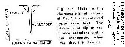
When most types of tubes are used in the circuits of Fig. 6-3, oscillation will stop when the output plate circuit is tuned to the crystal frequency, and it is necessary to operate with the plate tank circuit critically detuned for maximum output with stability. However, when the 6AG7, 5763, or the lower-power 6AH6 is used with proper adjustment of excitation, it is possible to tune to the crystal frequency without stopping oscillation. The plate tuning characteristic should then be similar to Fig. 6-4. These tubes also operate with less crystal current than most other types for a given power output, and less frequency change occurs when the plate circuit is tuned through the crystal frequency (less than 25 cycles at 3.5 Mc.).
Crystal current may be estimated by observing the relative brilliance of a 60-ma. dial lamp connected in series with the crystal. Current should be held to a minimum for satisfactory output by careful adjustment of excitation. With the operating voltages shown, satisfactory output should be obtained with crystal current of 40 ma. or less.
In these circuits, output may be obtained at multiples of the crystal frequency by tuning the plate tank circuit to the desired harmonic, the output dropping off, of course, at the higher harmonics. Especially for harmonic operation, a low-C plate tank circuit is desirable.For best performance with 6AG7 or 5763, the values given under Fig. 6-3 should be followed closely.