GS35b Amp
GS35b HOMEBREW 50MHz AMPLIFIER
Power Supply Schematic
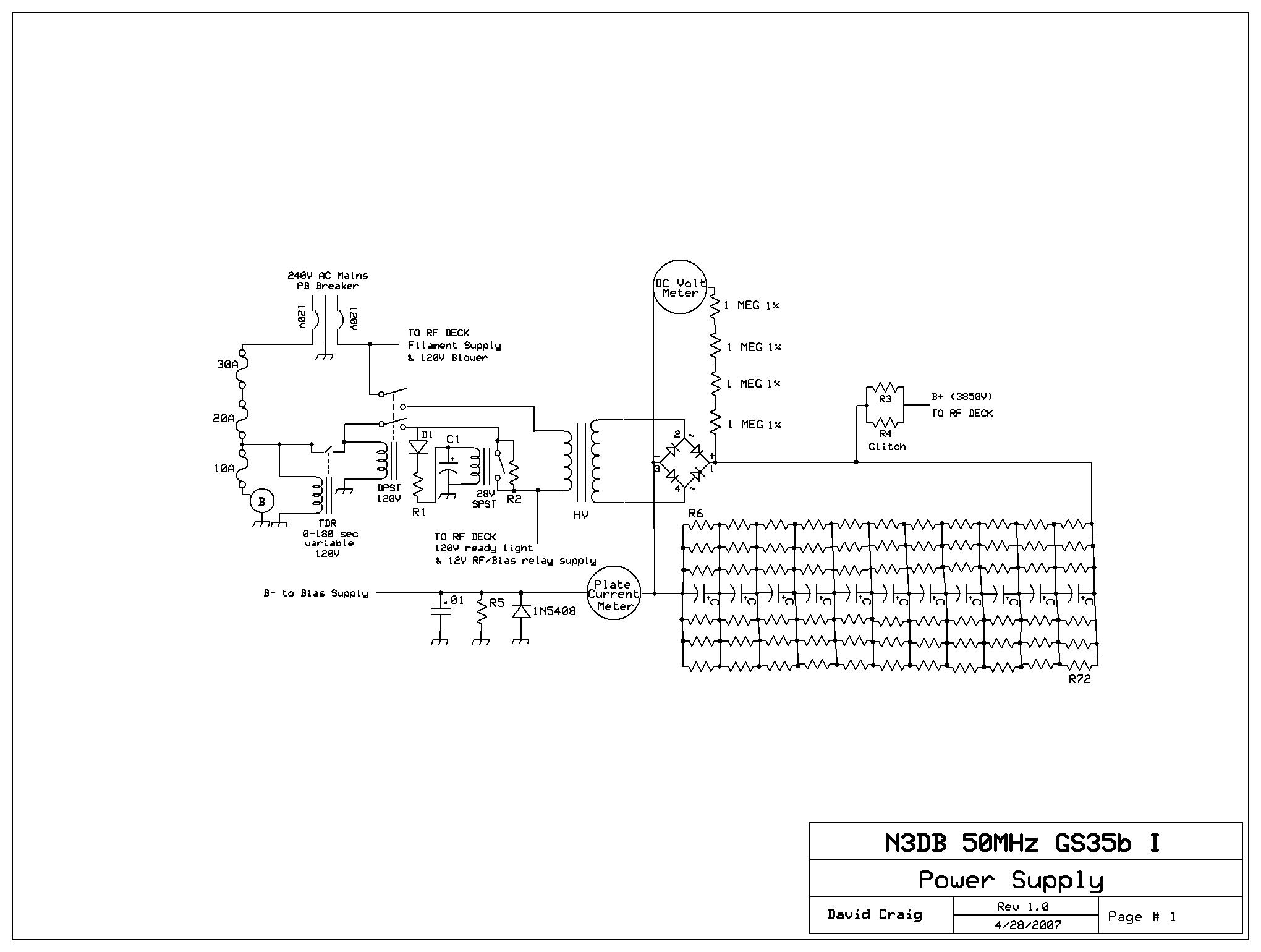
POWER SUPPLY CIRCUIT DESCRIPTION
The power supply used is a converted ETO MRI supply purchased in Dayton 2005, which is really 2 power supplies in one.
The "high" voltage side of the supply is built around 11 Mallory filter capacitors at 2,200 uf each with 6 equalizing/bleeder resistors (R6-R72) across them rated at 220,000 ohms at 2 watts each. The "medium voltage" supply contained in the same chassis (with over 3kv of separate capacitors and a separate full-wave bridge) goes unused (for now anyway). The regulation in this supply FAR exceeds what is truly necessary for this amplifier, and takes a large amount of time to bleed off after power-off. DO NOT EVER pull the cover on a HV supply or otherwise touch anything until you are absolutely sure the capacitors are fully discharged (which can take many minutes). Use a "chicken-stick" just to be sure! REMEMBER, these voltages are lethal. NEVER, EVER attempt this type of project until you have a working knowledge of the circuitry involved. Better still, if it is your first project, do so only under the tutelage of someone you KNOW is competant. K3TKJ & KA3SVF elmered me through the early "mysteries" of power-supply construction, and very very patiently I might add. I am still here so they did well.
Three wire 240VAC is fed to the supply via a 20amp Potter & Brumfield breaker. Mains common is grounded to the chassis internally. A double spade connector from one 120v leg of the breaker provides AC for the filament supply & RF deck blower, both of which activate when the P/B breaker is turned on. The other 120V breaker leg feeds a daisy-chain of fast-blow fuses which terminate with a tap to a 120VAC fan used to cool the power supply components. The fan was original to the ETO, and blows massive amounts of air. From a 20 amp tap a 0-180sec variable time delay relay provides the necessary time for the GS35b cathode to get up to operating temperature before HV is supplied to the tube anode.
Upon tripping, the TDR feeds 120VAC to the coil of a double pole single throw high-current relay. Each pole of the relay carries a 120VAC leg of the 240 mains. Once tripped, one 120VAC pole from this relay is tapped to feed a 28VDC high current SPST relay power supply made with some 25watt cement power resistors, a 1N5408 diode and an electrolytic capacitor. Using the resistance of the relay coil as part of the calculation, with an appropriate ohmage value this circuit also serves to time-delay the 28v relay long enough (~ 1-2 seconds) to provide a soft-start for the HV transformer (which is why this relay is necessary). A solid-state TDR would also work if you have one. In the interim, as soon as the DPST high current relay trips, R2 (an Ohmite 25w 50ohm wire-wound) shorts the 28V relay contacts and provides a limited mains load to the filter capacitors for the length of the delay. After the 28V relay trips, R2 is bypassed & full 240V mains flows to the HV transformer.
The HV transformer, now under power, converts the 240VAC mains to around 2700VAC at roughly 1 amp (I am unsure of the transformer rating, but remember, necessary current will be drawn until the transformer overheats & shorts, so if you have a choice be sure the transformer is rated for at least 1.2 amps for this tube). The transformer feeds the full-wave bridge diode configuration on a large PC board mounted above the capacitor bank. The ETO supply is from the early 80s and uses one large diode for each leg of the bridge. I have been unable to find a spec sheet or otherwise cross-reference the part number, but given the overall engineering of the supply I am certain they far exceed the necessary specs of the PS (as proved already during a tube flashover in the opening stages of working out the "kinks"- it took out meter protection diodes and a Z-50 inductor I had in the tank circuit at the time but never bothered the bridge diodes at all). Legged strings of 1N5408 diodes or large bridge diode "blocks" could just as easily work, just be sure the components used on each leg of the bridge match the other legs.
The fullwave bride rectifies the ~2723V AC and charges a LARGE capacitor bank mounted on a separate PC board below the bridge board to 3850VDC. The capacitors consist of 11 massive 450V Mallory aluminum electrolytics in series, 2,200 uf each (2,200/11=200 uf en toto). They are each equalized & bled by six 220k ohm 2 watt carbon composition in parallel across each capacitor. The whole assembly is mounted on its own PC board and the capacitors are staggered to allow ample airflow. From an engineering & design standpoint I could have omitted the parallel resistors on the schematic (using a single R across each instead) but for clarification of the supply design & for my own edification, I included them.
On the positive side of the diode bridge a string of four 1 MEG precision resistors supply a reference voltage for a Hoyt 0-5kv voltmeter. The B- side of the board is fed thru a 0-1 amp Hoyt ammeter in series. I use the built-in shunts on both meters & have had no problems- I believe they are reasonablely accurate. A 500ohm 10 watt ceramic resisitor, 1N5408 diode and a 3kv .01M capacitor float B- above chassis ground potential on the power supply side, and this "float" scheme is repeated on the RF deck side of the B- feed. It really makes no difference whether the combined "float" components are split between the PS & the (physically separate boxes) RF deck, but I chose to do it that way for convenience. This float scheme is identical to that used in the Lunar-Link LA amp series.
B+ is routed to the RF deck via a Millen connector & high voltage routing wire (I plan to use a shielded coaxial connector for amp #2). Glitch resistance is provided by 2 paralleled 25 ohm 50 watt vitreous enamel power resistors mounted directly in front of the HV supply fan. This is overkill, but I had them so I used them. The other control & return voltages are tapped via a Molex 8 pin connector to the separate RF deck. In some cases a 120VAC neutral wire has been routed back to the power supply deck- this is probably overkill as there is a large chassis to chassis common ground, but redundancy can't hurt. Remember, when selecting connector plugs, be sure to consider the "idiot" factor- never use plugs which, in the event of an "unconnected" powerup, allow direct contact to an unshielded live voltage source. This means, in my case, a female connector in the HV Supply chassis and a male connector in the RF deck chassis. In this fashion it is more difficult to contact the control voltages in the event the PS is turned on with an unpluged molex. Finally, both the DC voltmeter and the ammeter have a pair of 1N5408 diodes and a 1kv .01 capacitor (the latter for RF filtering) across the leads to protect them from tube flashovers & other glitches. Take it from me, DO NOT OMIT this protection, unless you like purchasing new meters after a tube flashover (which are fairly common with these NOS tubes). My first flashover ruined one of the 1N4006 protection diodes in my plate current meter (& melted a pin on the bridge diode board) but did no other damage to the power supply. I replaced the $.50 protective diode/capacitor circuitry & presto, ammeter back to proper operation. Sure beats replacing a $35.00 meter.
RF Deck Schematic
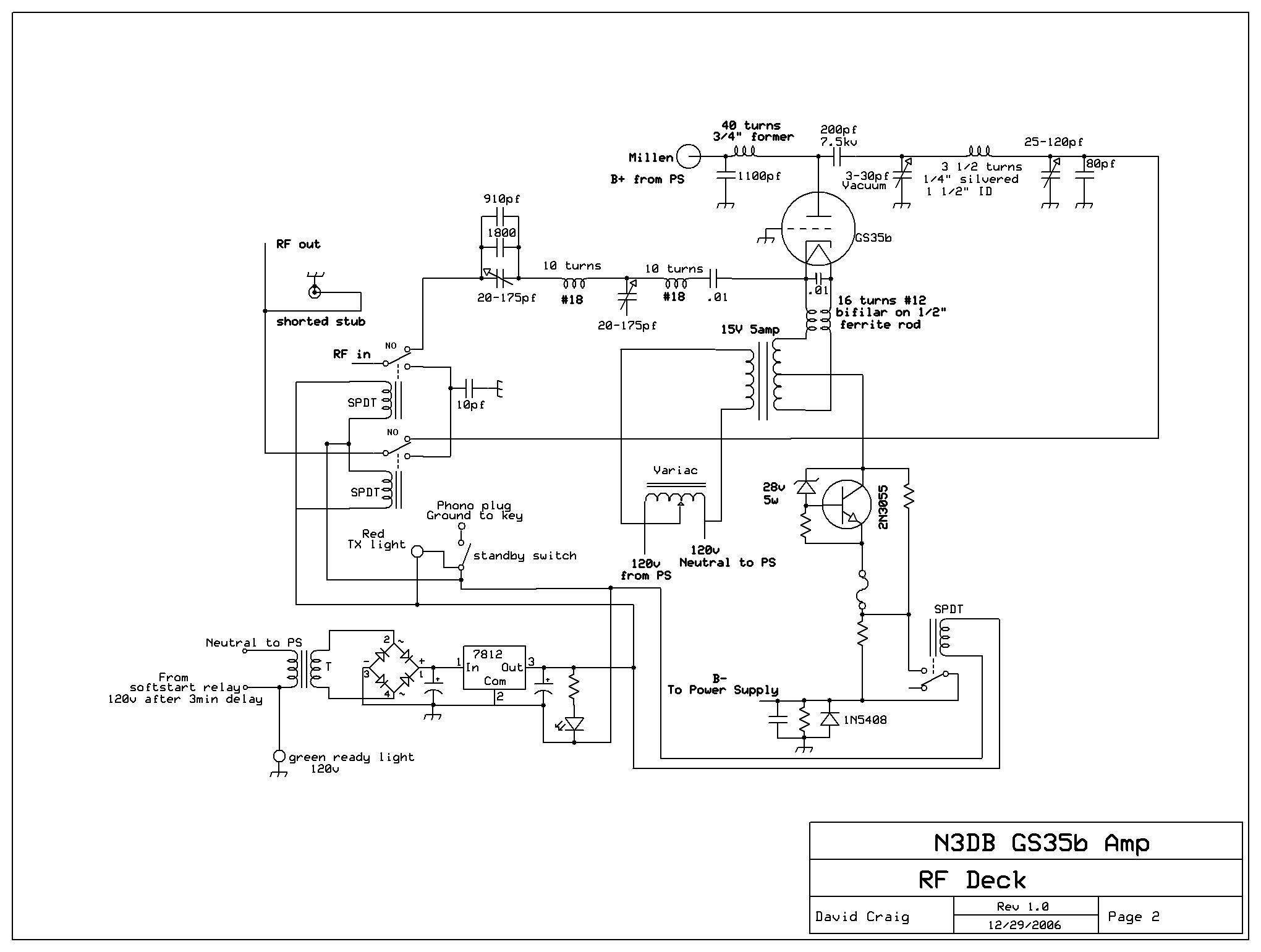
RF DECK DESCRIPTION
The RF deck in this project is in the traditional configuration- a split deck, with anode components shielded from the cathode compartment by a solid aluminum plate. All input, cathode and control circuitry is housed in the pressurized lower compartment. The Molex plug enters the chassis via the lower compartment. When the PS main breaker is turned "on" 120VAC flows to the RF deck, ending at a terminal strip. The 120VAC blower, tapped from the strip, immediately powers up, as does a 0-130 volt rheostat which is mounted to the front panel chassis via a thru-mounted adjustable output bolt & screw. This allows the mains supply voltage to the cathode supply transformer to be adjusted from the front of the RF deck during operation. The rheostat supplies AC to a 15 volt 4 amp center-tapped transformer used for the filament supply. The 15 volt transformer secondary is wired to two feedthru capacitors mounted on a piece of angle aluminum, which serves to add additional RF filtering & also supports the bilfilar filament choke. At each feedthru capacitor to transformer secondary junction, a wire is soldered which leads to a corresponding test point which is also thru-mounted to the front of the RF deck. The test points allow me to use my Fluke voltmeter to accurately measure filament voltage, which for a GS35b must be between 11.9 to 13.3 vAC (12.6V nominal). You could just a easily add an AV voltmeter to do the same thing, but again I used what I had. Though I have seen GS35b amplifiers using simply a 12.6V center-tapped transformer for filament supply, the rheostat has a number of advantages. First, no filament soft-start is necessary, as the rheostat protects the filament from excessive start-up current inrush. Second, and more importantly, one can be assured that the tube is running within the proper voltage range, and (maybe) could extend a soft tube's useable life by increasing filament voltage after it softens. It would be slightly more accurate to wire the testpoints directly to the cathode band clamps, but in practice I found the measureable difference to be negligible.
The filament choke I use on this amp is built around a 1/2" ferrite rod with roughly 14-16 turns (bifilar) of 10 gauge enamel wire. This is surely overkill as unlike some other triodes, the GS35b draws a maximum filament current of merely 3.25 amps. Some European builders also leave out the ferrite rod as well. On the cathode side of the choke a 3kv .01uf soldered across the choke wires provides additional RF filtering. The filament leads are each soldered to a corresponding homebrew cathode clamp made of brass strap. The base of the GS35b has a series of filament cooling holes near the base, and a screen on the base itself, so be sure to fabricate a base clamp with thin strap so they are not choked off. The second circular band directly above the base carries one side of filament AC & is fed RF drive.
Drive enters the RF deck via a chassis-mounted SO239. RG58 teflon from the input connector feeds RF drive to a K5AND relay board, which is made with 2 SPDT Schrack 12v relays with a 10pf silver-mica capacitor to ground which helps with "amp bypass" VSWR. Dick's board is discussed, et al, in this QEX article. A 12 volt regulated power supply for the Schrack relays & a Potter-Brumfield 12v relay used for bias switching, was built in the bottom chassis using junk box parts & a 14 volt transformer from an old tape recorder I had laying around. The 12v supply recieves 120vac only after the HV Supply soft-start activates, thereby preventing drive from being applied before HV is present on the plate. On key-down, the RF & bias relays are keyed to ground by the driver rig via a phono plug thru-mounted on the back of the RF deck chassis, to which all the -12v sources are connected. A 12volt Red LED array is also grounded upon keyup and serves as the transmit light for the amp. When the Schrack relays close, RF drive enters the tuned input "Tee" circuit thru roughly 3000pf of silver-mica & ~175 pf of variable capacitance in series with the drive. Drive then passes thru a ten-turn inductor which feeds a 20-175pf variable capacitor, one side of which is grounded, and which is adjustable thru the back chassis. In the Tee configuration, this capacitor will have the most effect on input tuning, providing a noticeably sharp SWR dip. This variable cap then feeds another 10 turn inductor mounted at right angles, which in turn feeds a 3kv .01uf Ceramite disc capacitor in series. Finally, the Ceramite is mounted to the 2nd tube cathode clamp via a brass nut, supplying RF drive to the tube.
Upon being grounded by the transciever key line, a 12v P&B relay shorts out a bias cut-off resistor, allowing current to flow. The circuit I used is, I think, originally from Bill Orr, and available online at KK5DR's amp builder page. I chose to utilize a 5 watt 28V zener, but plan to change it out with a 33 volt zener at some point as my idle current is a bit high at .200 - K8CU, K7CW and others use 32V zeners and see a resting idle current in the .120 range. I utilized a Motorola 2N3055 in a TO-3 package & assembled the entire bias circuit on a scrap piece of breadboard. Lots of air flows in the pressurized lower compartment where the bias circuit is mounted, and thus I didn't bother to heatsink the transistor. Only time will tell if this was the right decision, but it works fine so far. I didn't bother thru-mounting the bias fuse either, though I used a salvaged chassis-mount fuse housing so I can if I choose to later. As an avid cw operator I am happy with the fixed bias circuit, though after 2 years of using graphite 3-500Zs in my converted SB220 I am genuinely interested in trying a combination fixed/dynamic bias circuit so I can operate contests without the AC on in January.
The tube socket used in this amp was designed by K3TKJ. Al's original idea was to mount the tube horizontally, so he designed a grid-clamping socket that resembles an internal combustion engine journal bearing and block, with the GS35b grid ring acting as the "crankshaft". A retired NASA employee with a penchant for precision metal engineering milled the block to very tight specifications. Using two allen-head screws, the massive tube blocks holds the grid ring snug, forming a very good electrical connection. Because of the intended horizontal tube configurationj, one side of the block is longer than the other. After extensive mockup with a sheet-aluminum chassis, I determined that a more traditional vertical tube configuration was the way I wanted to go, so I added four 1" wide pieces of angle aluminum stock to the sides of the block to allow me to bolt the tube vertically to the middle chassis plate while permitting it to stand off from it for proper airflow. Given the sockets original design parameters this configuration is a bit difficult to work with, but does provide a good solution for mounting the tube. I also suspect the 1" thick grid block acts as an extra "heatsink", helping to keep the tube cool.
The RF deck itself is, compared to the pressure compartment, quite barren. The tube anode protrudes thru the top of a 4" hole in the RF deck base, and a piece of 4" ID PVC is used as a chimney. As I have my tube mounted a sufficient distance from the chassis wall the PVC works fine. An aside- you can easily test unknown or "iffy" dielectric materials for compatability in a strong RF environment by placing them in a microwave oven for 30 seconds or so- if they get hot, smoke, or both, DONT USE THEM. Make sure you double-double check this too: The first HV choke I used was wound on a threaded rod I thought I had tested. As you can see here I was wrong. The HV choke worked great, until the heat from the brass nut & screw at the base of the choke caught fire & melted. This RF unstable 26 turn-wound HV choke former, once overheated, also caused a peculiar RF "hash" in my reciever which I could not track down. After I rewound the choke to 40 turns with a 3/4" fiberglass former the "hash" problem disappeared. The B+ Millen connector feeds directly into the top RF Deck. In my original design I used a ~2" piece of HV line from the Millen to feed a 100pf 7.5kv RF bypass doorknob cap grounded to the chassis and an Ohmite Z-50 choke with fairly long leads to feed my HV choke. After changing the HV choke to the fiberglass 40 turn mentioned previously, in short order I then blew up the Z-50 (they sound like a cherry bomb in case you are interested). Moral here- add a glitch resistor in series with B+ line in the power supply to limit current surges, and don't use a 1 amp inductor with a tube rated for 1.2-1.5 amp anode current. Also, for RF bypass, 1000pf is really the minimum capacitance value you want to use, and you will be well-served to keep the B+ to bypass capacitor to HV choke lead length to the smallest you can. In my case, I had a 700pf & 400pf 7.5kv doorknobs onhand, and thus I paralleled them as close together as I could using flat brass strap, and mounted them on the back chassis wall as close to the Millen connector as I could. This reduced the HV connector to cap lead length to ~1/2". I then mounted the HV choke on the chassis wall as well, and by doing this & eliminating the Z-50, the HV choke has around a 3/4" lead length to the paralleled RF bypass capacitors. Conveniently, the choke former is threaded, and 40 turns was long enough to bring the end of the choke to within an inch of my homebrew brass strap tube anode HV connector. K8CU, K7CW and others use at least 2 RF bypass capacitors, but by keeping the Millen to Cap to HV choke leads very short, you can eliminate the need for an additonal 1000pf (or better) doorknob. I have since learned that the Linear Amp UK 6m "Discovery" model, which uses a GS35b, uses a similar tank configuration.
Using flat strap for low inductance, the anode clamp is tapped by a short piece of thinner & more flexible strap to feed the plate blocking capacitor, a 7.5kv HEC 200pf doorknob. The cap has a sufficiently high RF current rating & is physically the same size as a 15kv cap, but a 15kv rated model would be better. For this amp I chose to use a simple PI ciruit, with a 3-30pf vacuum variable for tuning. As noted by K8CU in his great QEX article in the Up Front column, this capacitor may be omitted. Paul, K7CW only uses a loading capacitor in his 50MHz GS35b, and gets great results. All it takes is a more precise adjustment of the tank coil to allow the amp to load properly. In my case, I also utilized a somewhat lower than desireable loading capacitor- a 26-100pf rated at roughly 2kv. In the beginning stages of getting tis amplifier up & running, it became apparant that 100pf is not enough capacitance to load the amp properly. Instead of looking for a more suitable air variable, I used some .03125 teflon sheet I had onhand and a piece of brass plate to fashion a fixed capacitor in parallel with Load. If you use thin brass sheet, cut the brass plate for a larger capacitance than you want as it WILL bend. I cut mine for roughly 120pf, and after scoring & bending, the best I could get was 86pf (measured) from it. If I added a stiffener to the back of the brass I imagine I could get more capacitance, but it seems OK. I mounted the fixed cap via two stainless steel bolts to the side chassis wall & used silver solder to install a brass strap to parallel it with the load capacitor. I found suitable PTFE insulators for the bolts & used teflon nuts behind them to further isolate them from the brass. I over-sized the holes in the brass to add an additonal "comfort" level. The tank coil between the Jennings tuning cap & the load caps in parallel is made of silvered tube roughly 3/16" in diameter. The coil consists of 3 1/2 turns at 1 1/2" ID. Most GS35b amps, with the notable exception of the Discovery, use 4 to 5 turns on the tank coil, so be sure to cut it longer than you think it need be & either find the best tap point or expand or compress the coils for optimum efficiency. Remember though, DO NOT USE BRAID to tap the coil. Braid in a 50MHz RF deck introduces all sorts of stray inductances that will effect efficiency. Use brass, copper or silver strap for as many tank connections as you can. Tank output RF is tapped from the tank coil as close to it's junction with loading capacitor as I could reasonably get. The coax I used to tap it is a high RF power teflon shielded coax similar in size to RG58 I was given by KG4HOT. I removed the outer shield & braid near the end & drilled a small hole thru the RF deck chassis bottom to access the coil/cap junction. Though I think it would be better to drill a hole in the coil thru which the center conductor could be soldered, I just soldered mine to the side of the coil. It seems to work OK & is easier to remove.
The high power coax tap from the tank passes thru the hole in the chassis & terminates on the RF out relay pin on the K5AND relay board. It is grounded via the coax shield braid to both the chassis & the board. Amplified RF transits the keyed NO contact and exists the amp via another short run of high power coax with a thru barrel-mount N connector. Though I could have used a Z-50 or other inductor at the connector output for a safety choke, I chose to add an N "Tee" connector & use a shorted stub for protection in the event of a plate bloacking capacitor failure. You MUST add either the stub or a choke to ground- the shorted stub has the advantage of providing harmonic suppression so I went with it. In my next amp I may try to fit the entire stub on the inside of the pressure compartment as it would help clean up the look of the amp. For info on measuring a shorted stub, see the K8CU webpage. Finally, I am in the process of building a Low Pass filter for the amp. K8CU's website has a relatively low-cost version, and K1WHS also has plans for what he calls a "MOJ" Low Pass filter. One of these 2 designs will be mounted in an aluminum box on the RF side of this amp before long.
THOUGHTS, "SHOULD-DOS" & "GLAD I DIDS"
In this basic and simple monoband amplifier I have excluded various features that you may be better off incorporating. No grid current meter is used- having one would definitely make calculating efficiency & noting exceeded operating parameters a lot easier, though the GS35b is a hearty tube that is hard to hurt. Also, this amp has no built-in sequencing as yet- this is more the result of impatience than anything else. Granted, the amp probably "hotkeys" as a result, but many commerical amplifiers contain no adequate key delay circuitry, so I am going to use it for a while as is & see how the relays hold up. I have been working on an N6CA time delay relay circuit (see the ARRL handbook) with additional mechanical 12v relays to isolate the switching transistors, but have not yet completed it. Also, no grid current cutoff control circuitry exists, nor do I have a blower safety cutoff in the event of airflow failure. For the last 6 months, the bottom line was getting the amp QRV at minimal additional expense, so neither of the latter was seriously considered. For my second GS35b I likely will add both. One thing I did "last minute" that I am happy about is to add a standby switch. This "last-minute" addition, which is nothing more than a manual switch installed between 12V keyed grounds and the amp "key" phone jack, will certainly be a part of all my future amp builds. Currently I am getting roughly 1200 watts key-down out of this amplifier with around 75 watts drive, and I have not yet completed adjusting/tuning the tank coil for maximum efficiency nor maximizing the input tuning circuitry. I am very satisfied with the current output, but expect it could be improved dramatically if I spend more time on the tank. Finally, DEFINITELY provide for easy measurement of filament voltage- I am glad I did. Mains supply to my QTH SUCKS- since May 2007 I have measured filament voltages as high as 13V and as low as 12V, and the ability to put the tube back into its efficient and safe operating voltage range has been a blessing. With the tube I am using I find efficiency peaks at around 12.7 volts. Lower than this & the output drops to as much as 100W, definitely a recipe for premature tube failure.
CHANGES
Never being satisfied with the status quo I made a few modifications to this amp over the last few months. First was to add an L to the tank circuit in the attempt to improve efficiency. It didn't, or at least I didn't monkey around with it long enough to realize a benefit, but it did reduce the necessary load capacitance and thus the homebrew brass & teflon capacitor in parallel with the variable load capacitor was removed. Secondly I took a turn off the first L on the tuned input circuit and shortened the leads, which helped lower the input swr to a more acceptable level. For the next amp (in progress) I am tossing the "T" input entirely and using a Pi network instead as virtually every GS35b "T" input I have seen, played with or built has had an unduely sharp tuning peak. Check out every photo you can find on the web of a T network tuned input variable cap on a GS35b amp and you will notice it is at the "edge" of "just barely" meshed. Thirdly, I am convinced the HV transformer I am using is too light in current for this application. Despite the unduely high capacitance of the HV supply, the current demands of the tube are saturating the transformer and dropping B+ lower than it should be. Running the tank at peak efficiency taxes the transformer to the extreme and with my less-than-adequate blower creates a combination of thermal drift and DC voltage variation that is impossible to keep up with. The law of diminishing returns has caught up with me- the more I improve the efficiency the bigger the drop in B+ and the hotter the tube becomes. My solution, which isn't the greatest but works fine for me is to load the tube a bit and keep output at around 1000 watts key-down. Doing this has allowed me to run the amp continually in contest-mode with no problem for many hours straight. If you want to really maximize the output of this tube you need to keep B+ at 3500VDC or better under full load, unless you have a rock steady choke input supply over ~ 3200V that doesn't drop more than 100-150V under full load. Given this limitation I have decided to leave this amp "as is" and use it for the 2007 E season, after which I hope to have completed my second 50MHz amp project. This project, which I am documenting with many photos as I go, is a "floor model" one piece amp on rollers. It is centered around a 2800,2875,2925,3000VAC 2amp CCS Heritage transformer I picked up from WA1JOF, and will (inter alia) utilize a PiL tank circuit with a tuning flap to eliminate the expensive 3-30pf vacuum variable, RJ1A vacuum relays, a higher-volume blower, and some additional safety circuitry to protect the tube.
Visitor number
 since Feb 2007