
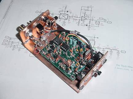
Picture 1. R-M/40 in the Novelty Chuck Wagon Enclosure
Rock-Mite Experiments ñ Chuck Carpenter, W5USJ
Download MSWord Document (in ZIP file format)
(right click link and choose "Save As")
Tips listed below were found useful for performing repetitive experiments involving component changes. These tips may also prove useful for otherwise unmodified Rock-Mite operation. See the experimental chassis picture.
Chuck Wagon ñ The first home for the R-M/40 was in a novelty enclosure.
Picture 1. R-M/40 in the Novelty Chuck Wagon Enclosure
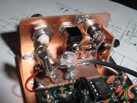
Experimental PCB Chassis ñ A chassis fashioned from PCB is where the R-M/40 now resides. The novelty enclosure was too clumsy for making modifications and doing experiments. Turning the board around in the enclosure provided easier access to Y2. An extension was added to the RG-174 coax too.
Picture 2. R-M/40 Setup in the Experimental PCB Chassis
Beacon on 7122 and 7085 kHz ñ The R-M/40 was setup for operation as a beacon on two separate occasions. The keyer is a PK-3 in beacon mode with a TE-NE-KEY. It was in beacon mode for about an hour each time and I received reports varying from 449 to 569 up to about 670 miles. With the PK-3 keyer in control, the sending speed can be varied and one report said copy was better at faster speeds.

Picture 3. R-M/40 Setup for Beacon Operation with PK-3 Keyer
Note: The following information is based on empirical design with a sample of 1 ñ YMMV. Machined DIP pins were installed at key component locations to facilitate changing parts.
This section is about simple experiments to shift the frequency of the Rock-Mite/40 Y2 crystal. For a more elegant and sophisticated VXO, check out NB6Ms excellent work posted in the Rock-Mite Files.
My first idea using a trimmer and choke in series with Y2 didn't work too well. It caused funny things to happen during transmit. As a result, the R-M/40 Y2 circuit was changed to series capacitors or inductors only.
An 8-100 pF trimmer was added in series with the 7040 Y2 crystal. The frequency range worked out to be about 7040 to 7043, max to min on the trimmer. It was neat to be able to tune to some of the weaker signals.
Picture 4. R-M/40 VXO Manhattan-Style Assembly on a PCB Platform
The measurements are relative, not precise. They are as close as I could come listening for zero beat with my FT-847 and using a 25 Hz filter. Power is measured into a 50 ohm load using a WM-2 meter. [25 W 50 ohm load flat from 1800 kHz to 150 MHz.] L and C values were measured with an AADE L/C II meter. Measured values are shown in parentheses.
Initial frequency as-built [no added parts] is 7039 kHz. Nominal power output is 500 mW.
DIP switches, DIP sockets and component headers can be used to assemble and switch component values. Assemble a small daughter board and mount it close to the Y2 connection points.
| Fixed Capacitors ñ measured close to marked value | ||
|---|---|---|
| Capacitor | Frequency kHz | Note |
| 20 pF | 7041.15 | |
| 15 pF | 7041.7 | |
| 10 pF | 7042.6 | |
| 5 pF - | 7044.25 | |
| 3.3 pF | 7045.3 | Power dropped to ~450 mW |
| Fixed Molded Inductors | ||
|---|---|---|
| Inductor | Frequency kHz | Note |
| .68 µH (.8) | 7038.9 | |
| + 68 µH (1.57) | 7038.8 | Two .68s in series |
| 4.7 µH (5.11) | 7038.4 | |
| Total All (6.76) | 7038.2 | Two .68 and 4.7 in series |
| 15 µH | 7037.4 | |
| 22 µH | Power dropped to ~150 mW | |
| Variable Trimmer Capacitor 8.5 - 100 pF (8 ñ 119) Jameco 94449 | |||
|---|---|---|---|
| Frequency pairs are the result of pressing the shift button to obtain the offset. This test used three crystals marked 7040, 7083 and 7122 kHz and measured as follows: | |||
| C-min | Shift Hz | C-max | Shift Hz |
| 7043.33 | 7040.08 | ||
| 7042.88 | 450 | 7039.37 | 710 |
| 7087.6 | 7083.9 | ||
| 7087.15 | 450 | 7083.07 | 830 |
| 7128.3 | 7124.66 | ||
| 7127.75 | 550 | 7123.82 | 840 |
An air variable with a shaft would allow developing a calibrated tuning dial. I have some ancient mini variables marked 30 pF. A mounting isolated from ground would be needed. Might be worth a try.
Whatever you add to the Y2 circuit, verify that output power remains close to the same. This indicates that the oscillator and buffer drive levels are probably still OK.
Note: One other trimmer was tried with poor results. A smaller part, marked 8-50 caused strange results. Useful adjustment was limited to the lower 1/3rd of the range toward C-max. Power dropped off markedly in the upper 2/3rds of the range toward C-min. Other parts of the same type did the same thing. They seem to work fine in L/C tuned circuits.
For conversion to 30 meters and subsequently to 15 meters, an R-M20 was built and installed in a second enclosure. Machined DIP socket pins were installed in the locations of changed parts. This setup produced a 1470-mile beacon report and QSO on 15 meters.

|
30 Meters(some parts are included in the 20 m kit) |
||
|---|---|---|
|
~600 mW output at 13.8 V DC ~680 Hz shift No noticeable drift was experienced from power on. |
||
| Part ID | Value | Note |
| Y1,2 | 10.106, 10.116 MHz | (QRPp-I and NorCal respectively) |
| D5 | 8.2 V zener | |
| C10,11 | 47 pF | |
| C12 | 39 pF | |
| L1 | 6.8 µH molded choke | (values from 4.7 to 15 didn't seem to affect performance) |
| L2, 3 | 1.2 µH molded choke | Alt. 20t #26 on T37-6 toroid cores |
| C15,17 | 220 pF | |
| C16 | 470 pF | |
Series molded filter chokes [.47 and .68] measured about 1.35 µH on the high side of the tolerance. Two T37-6 toroids were wound for L2,3 with 20 turns of 26 and substituted for the molded chokes. The toroids measured about 1.25 µH. No significant power level change resulted from using the toroids. [I had other uses for the chokes.]
One crystal used in the oscillator is marked 10.111 MHz and the as-built output frequency is low at 10.109 MHz. A 10 pF np0 cap was added in series with Y2 that raised the output frequency to 10.113. A small choke in series with Y2 lowered the frequency. Pairs of 10.106 MHz crystals from Brice [QRPp-I] and 10.116 MHz from Bruce [NorCal] were ordered to get closer to the QRP calling frequencies.
| 15 Meters (some parts are included in the 20 m kit) | ||
|---|---|---|
| ~300 mW output at 13.8 V DC ~950 Hz shift No noticeable drift was experienced from power on. |
||
| Part ID | Value | Note |
| Y1,2 | 21.060 | Available from QRPp-I |
| D5 | 4.7 V zener | Lower voltage for less shift |
| C10,11 | 47 pF | |
| C12< | 39 pF | |
| L1 | 6.8 µH molded choke | |
| L2, 3 | 0.68 µH molded choke | |
| C15,17 | 100 pF | |
| C16 | 220 pF | |
To get more output power on 15, it may be necessary ñ per Dave ñ to tweak the buffer (Q5) resistor values. So far, no buffer changes were made with my experiments. With 2 diode drops in series with the 13.8 V supply, power out was a little over 200 mW. [Forgot there was also a diode in my power distribution box.] Beacon mode and a QSO were at the 200 mW level.
Notes: