 |
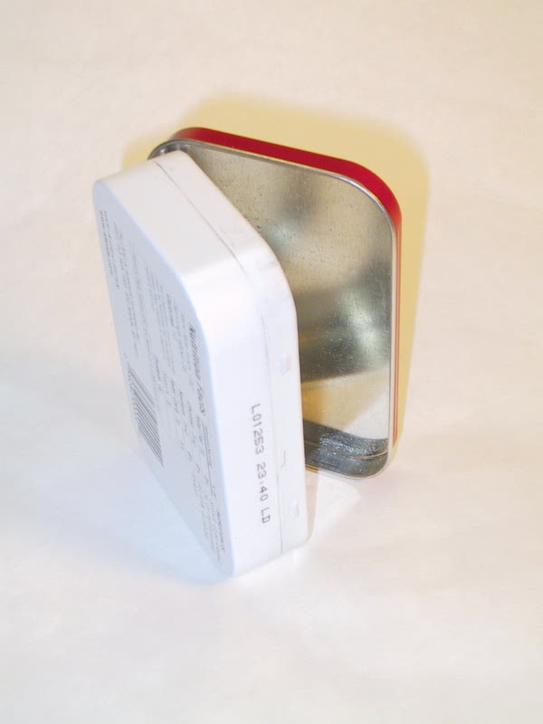
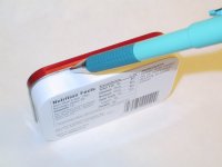
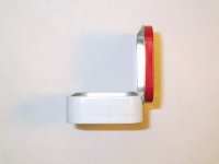
With cover closed, trace a pencil line under the cover, along the case edge (see next picture) |
 |
Result of pencil tracing above. |
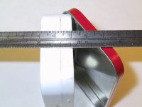 |
Note there is about 1/2"/12mm of space to position controls, connectors, switches...etc. and not
have them interfere with the Altoids cover when closed. I found the common items switches, key/earphone
jacks, BNC and power connectors to fit just right if centered in this space. |
 |
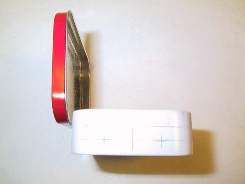
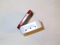
Here is how I laid out my "Rocky
Mountain Rock-Mite's" power, earphone and key jack.
First I drew a line half way between the bottom edge and the traced cover line (see above)
Then I marked the center of the line (large/dark vertical line) this will be for key jack
1"/25.4mm either side of the key jack, I marked the power and headphone jack locations |
 |
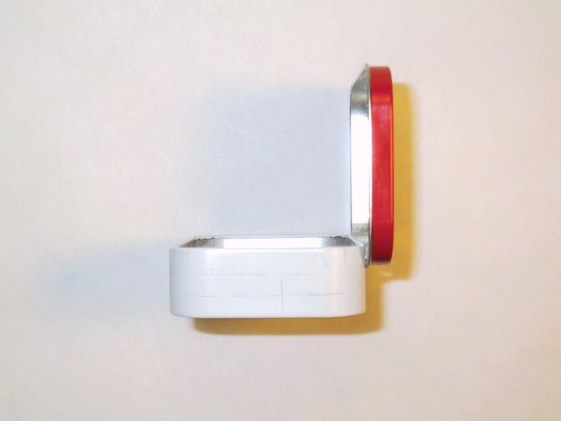
Opposite side marked for antenna location, centered between closed lid and 1"/25mm
from the right edge. (This spacing puts the antenna jack near the board pad, see my"Rocky
Mountain Rock-Mite")
NOTE: I do not show a location for the Keyer/Freq switch,
that will depend on the type and size of the switch you use.
|
 |
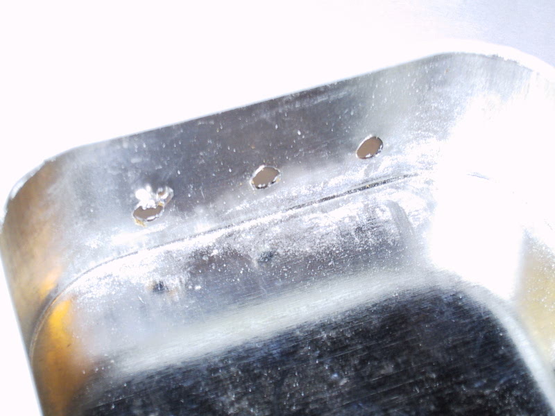
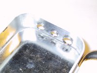
On this side I drilled 1/8"/3.5mm pilot holes. I have only a small hand drill, and
a small size results in a clean hole (see photo below) in the thin metal of the Altoids tin.
The hole will be enlarged with a hand-reamer and/or dremel tool |
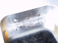 |
Backside of pilot holes above. A "backer board" was used during the drilling operation. |
 |
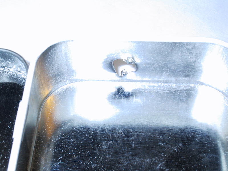
This is a 1/4"/7mm hole. Pretty ugly, it too was drilled with a "backer board".
I did this to illustrate what can happen to very thin metal when it is drilled. (espcecially
with a larger DIA bit) This is why I chose to drill small pilot holes, and then enlarge
them with a reamer or dremel tool. |
 |
Back side of hole above, YUK! |
 |
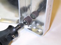
Very carefully and slowly, I worked the taper reamer in the hole for the antenna Jack.
Don't press to hard, you will bend the metal, and don't let the tool wobble. When you
are done you will have a clean hole. |
 |
Don't press too hard, you will bend the metal, and don't let the tool wobble. When you are
done you will have a clean hole. If necessary clean any spurs and flash with a conical tip on a Dremel tool. |
 |
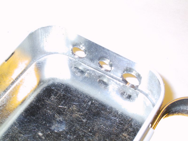
For this picture of the key, phones and power jack holes, I pressed the taper reamer harder,
and let it wobble a bit. Note the extra flashing/spurs around the holes. Don't stress,
it is easy to fix up, see below. |
 |
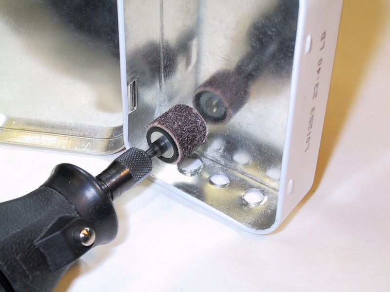
The small "drum" sanding bit available for a Dremel tool can sand this away quickly.
Don't rush, work slow, and don't over do it. Some touch up with a hand file or small peice of sandpaper
may be required. |
 |
Here is the result after the "drum" sanding, note a few burrs remain. Those will be
cleaned up as noted above. Also note the additional hole, it is for the Keyer/Freq. switch. |
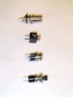 |
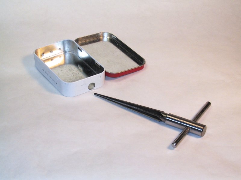
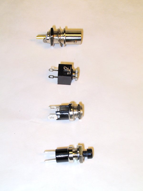
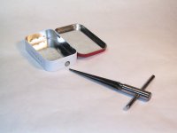
Here are the connectors and switch I chose, all ordered from
Mouser or
Digikey. From top to bottom:
- Cambridge BNC, Mouser# 530-CP-1094-AST, $1.31
(note the ground lug if needed)
- DGS 3.5mm phone jack, Mouser# 161-3402, $0.33
- SwitchCraft 2.1mm DC power-jack, DigiKey# SC1049-ND, $2.31
- Mountain PB Switch, Mouser# 104-0013, $0.79
|
 |
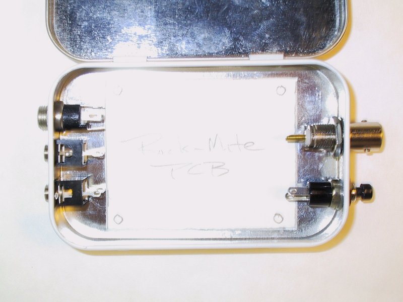
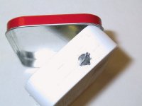
Finished product "almost" ready for a Rock-Mite PCB |
 |
When I have another Rock-Mite PCB, before I assemble it, I'll place it in the Altoids Tin;
center it like the white card in the picture; then mark and drill the mounting holes.
|