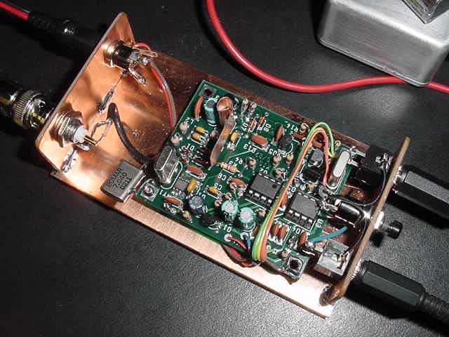
From: "Chuck Carpenter" <w5usj@...>
To: <rod@...>
Subject: R-M/40 Update
Date: Sunday, September 22, 2002 8:39 AM

Rod,

I've made a PCB chassis where the R-M/40 is now mounted.  The novalty [bottom of page--rc]
enclosure was too clumsy for doing any mods and experiments.  The picture
shows the assembly with a 7040 meter crystal suspended with its ground
wire.  A pair of 7122 MHz crystals are installed in the sockets for this
shot.  Power out to my Butternut vertical was about 400 mW according to my
Welz power meter on the 2.5 Watt scale. About the same as the power with
the 7040 crystal.
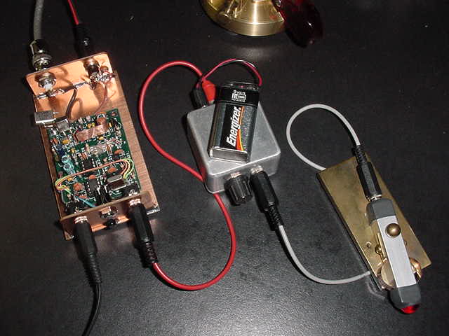
Sunday morning, 22 Sep, the R-M was setup for operation as a beacon.  The
keyer is a PK-3 in beacon mode with a TE-NE-KEY.  It was in beacon mode for
about an hour and I received report varying from 449 to 569 up to about 670
miles.  With the PK-3 keyer in control, the sending speed can be varied and
one report said copy was better at a faster speed.  About 20 wpm, I'd
estimate. I'll do a beacon mode again some time later in the evening.
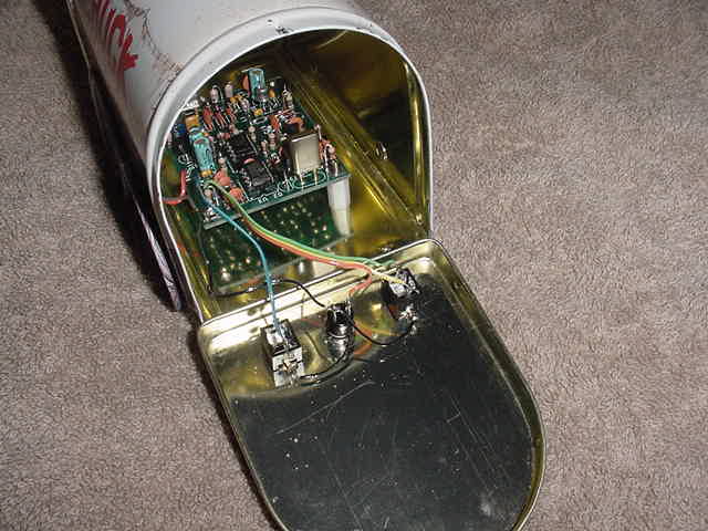
From: "Chuck Carpenter" <w5usj@...>
To: <rod@...>
Subject: Rock-Mite Files
Date: Saturday, September 07, 2002 5:39 AM

Rod,

Here's my entry for the Rock-Mite Files.  Had this special enclosure
sitting around for a while just waiting for something to put in it.

The headphone jack, pushbutton and keyer paddle jack are on the lower edge
of the front panel.  A BNC connector and power connector are on the back
panel.  You can see lower part of a whip (for show) above the back corner.
With this enclosure, a battery pack could be supported in the top part of
the wagon.

I have the board mounted on plastic standoffs on two corners.  Looking
closely, you can see that the mounting screw doesn't have a nut on it.  I
found that the PCB mounting holes are just a little smaller the the OD of
the 6/32 screw.  By carefully starting the screw, it formed a threaded hole
in the R-M plated-through hole.  There is sufficient strength to hold this
light-weight board in place using this technique.

Note that I use the term thread forming and not self tapping.
Thread-forming screws upset the metal to make the threads.  Self-tapping
screws remove metal.  Ground continuity was not destroyed by using thread
forming in the plated-through PCB mounting holes.  Self-tapping screws may
have removed too much metal in the holes.

Also, piercing was used to start the mounting holes.  In thin metals,
piercing is often used to provide more thread length.  For the mounting
holes in the bottom of this enclosure, the holes were pierced to slightly
smaller than the 6/32 screw OD.  The screws were held in place this way so
that it didn't take 3 hands to put the board in place over the standoffs.
You can also use self-tapping screws in pierced holes for more holding
strength.  Pierce them to about 1/2 the thread depth diameter.  To mount
larger parts, holes are pierced and then slowly and carefully drilled to
1/4 inch diameter.  A tapered reamer is used to make holes larger as needed.

...
Chuck Carpenter, W5USJ

From: "Chuck Carpenter"
To: "Rod N0RC"
Subject: Super Rock-Mite/40
Date: Tuesday, February 11, 2003 5:40 AM

Rod,

Got some good natural light yesterday and finished the pictures for my
Super Rock-Mite.  It includes the RMK chip and KD1JV filter board.  A VXO
board will be added too.  It will mount over the top of the R/M board next
to the Osc Crystal.

Need to stop messing around with the mods and pictures and do some
operating...   [g]

Thirty meters with 960 Watts will be my primary objective...   [g]

Make that mW!

The enclosure I used is a Context Engineering #4006B.  Got it from Frye's
off their mailorder website.