
Distributed Capacity Coaxial Dipole Antenna
I can recommend this antenna to anyone looking for a broadband/single band, easily constructed, dipole antenna. I have been using this type of antenna as my 40-meter antenna for over twenty years. I have built several of them over the years, and have always had good results. This antenna is more expensive to build as compared to a simple wire dipole antenna (coax is more expensive than wire), but has many desirable characteristics, such as broad bandwidth, and attenuated harmonics. I have finally arrived at what I consider to be a simple, inexpensive yet durable construction technique.
The components required (Figure 1) are:
(1) ½" "T" type PVC conduit box (it comes with a removable panel, gasket and attaching screws)
(6) ½" PVC closeout plug
(2) ½" PVC coupling
(1) ¼-20 X 2" eyebolt
(2) ¼ screw type eyebolt
(4) ¾" screw type stainless steel hose clamp
(1) SO-239 connector
Figure 1
Additional materials include: shrink tubing, solder, wire, misc. screws and nuts, and of course, coax cable. The coax cable can be any 50 ohm type but I have always used RG-58AU because of its lower cost. This article describes an antenna made from RG-58AU. If you use a larger size, then the drilled hole diameters specified here will need to be larger. All the parts shown in Figure 1 cost $15.50.
The first step is to cut the coax to the required length. Refer to the drawing for the dimensions "L" and "S, specified for each band. Allow one foot extra on the overall length "L". Find the center, by either measuring, or by doubling the coax, and aligning the ends. Measure each side of the center, dimension "S", to locate the point at which the coax shield and the center conductor are to be shorted. Mark the location.
I prefer to have a SO-239 connector installed in the conduit box. Figure 2 shows how I usually make the mounting plate for the connector. The plate is attached to the box with two small bolts, as shown in Figure 3. The extension sleeve at the center hole in the box will protect the feed line connector. I have used other methods of connecting to the antenna, but this is the one I prefer. I have, on other antennas, soldered the feed line directly to the antenna.
 Figure 2
 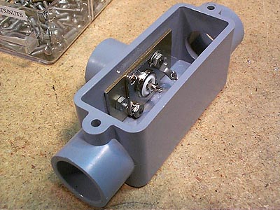 Figure 3
Drill a ¼" diameter hole through the conduit box on the side opposite the SO-239, and install the eyebolt (Figure 4)
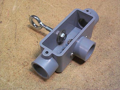
Figure 4
Drill a 13/64" diameter hole through four of the ½" closeout plugs (Figure 5). Using a hacksaw, saw two slits, 90 degrees apart and 3/8 deep in the outside end of the closeout plugs (Figure 6). Clean out all PVC chips from the hole and the saw cuts (Figure 7). This part is referred to in the following description as a "collet".

Figure 5
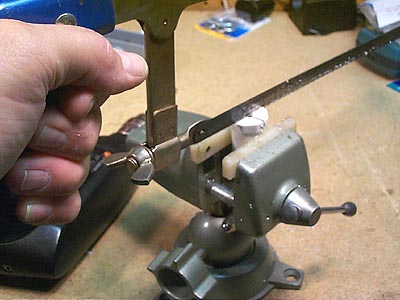
Figure 6
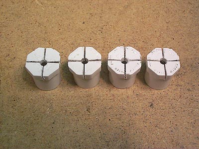
Figure 7 Collets
Assemble two antenna terminations as shown in Figure 7A, using PVC couplings, closeout plugs, collets, PVC cement and screw type eyebolts.
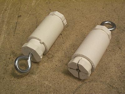 Figure 7A
Remove a one inch section of the outer jacket from the coax at the center of the length. Avoid cutting the coax shield while removing the outer jacket (Figure 8)
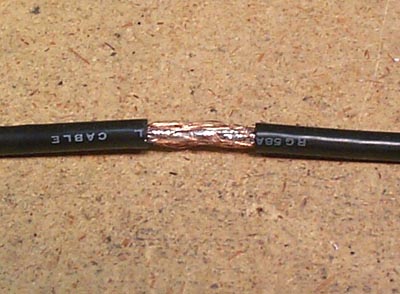
Figure 8
Cut the coax shield at the center, and double it back over the outer jacket (Figure 9).
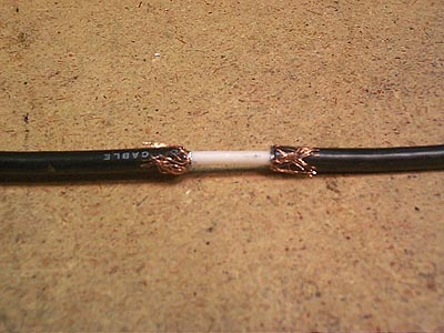
Figure 9
Wrap and solder feed wires to the coax shield (Figure 10)
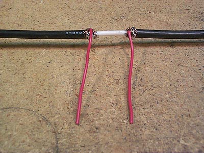
Figure 10
Install shrink tubing over the wires and coax shield (Figure 11)
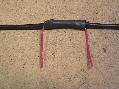
Figure 11
Feed the coax through the conduit box ( Figure 12) and solder one of the feed point wires to the center pin on the SO-239, and the other to the ground lug.

Figure 12
Slide a collet over each leg of the antenna until it is near the conduit box. Clean the outside of the collets and the inside of the mating sleeves on the conduit box with isopropyl alcohol. Apply PVC cement to the outside of the collets and install in the conduit box sleeves (Figure 13).

Figure 13
Install a clamp over each of the collets ends, and tighten until it firmly grips the coax (Figure 14)
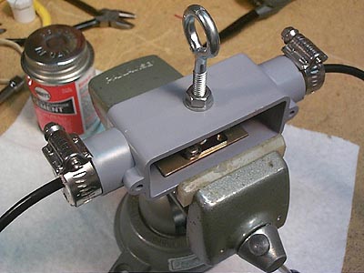
Figure 14
Install the conduit box cover and seal (Figure 15)
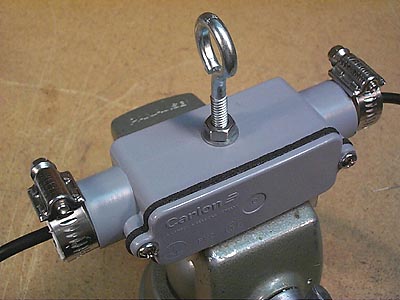
Figure 15
Remove a ½" length of coax outer jacket centered about the dimension "S" location. Be careful not to cut the shield. Separate the shield and remove the center conductor insulation. Solder a wire to the center conductor, then carefully wrap the wire around the shield and solder it to the shield (Figure 16)
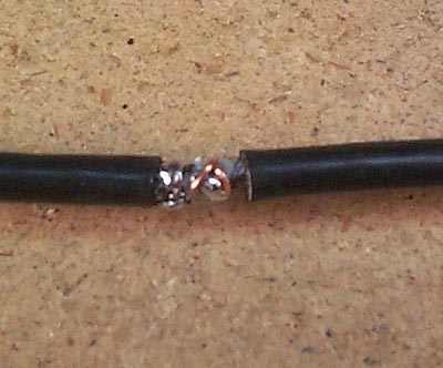
Figure 16
Install shrink tubing over the shorted area (Figure 17)
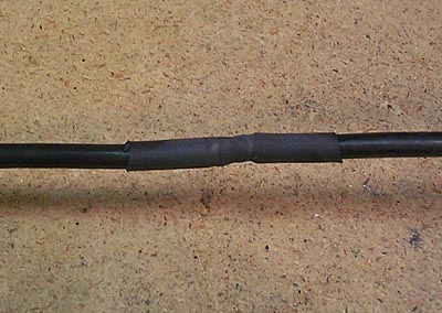
Figure 17
Remove ½" of the coax outer jacket from each end of the antenna, remove the insulation from the center conductor, and solder the coax shield to the center conductor (Figure 18).
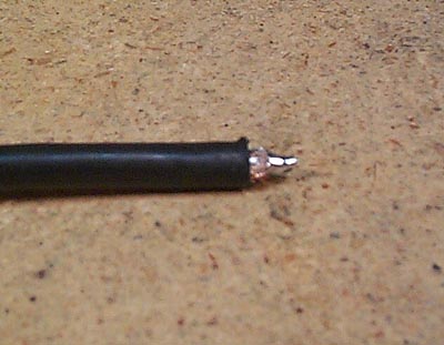
Figure 18
Push each antenna end into the collet end of the antenna termination assembly, and secure with a clamp (Figure 19).
 Figure 19
Attach a coax feed line to the antenna, and erect the antenna. Measure the SWR and if greater than 1.5:1.0, trim the antenna ends by loosening the clamp on the termination and removing the coax end. Cut approximately one inch off each end, re-solder the shield to the center conductor, and install and clamp into the end terminations. Repeat this process until a 1.5:1.0 SWR is obtained.
Once you have the desired SWR, apply a generous amount of silicone sealant at each of the areas where the coax goes through a collet. This will keep any water from penetrating the conduit box, and the terminations.
I hope you realize the same performance as I have had from this antenna. I presently have my 40 M antenna strung between my tower and a tree in the back yard, with no center support. The collets grip on the antenna is sufficient to keep it tight, although I plan on eventually providing a center support for it. The RF power capability of this antenna is a function of the type of coax used. The antenna described here will easily handle 100 watts.
This antenna may also be constructed without the conduit box described above. You could simply wrap the exposed feed points/shorts with electrical tape. The SO-239 connector could be replaced by simply connecting a length of coax feed line to the feed points. The problem in doing that is that when you split the coax outer jacket and shield, at the center of the antenna, you have significantly degraded the tensile strength of the antenna. But it will work because I have used the simple construction technique in the past. They just don’t last as long. The technique described in this article, reduces the tensile stress at the feed point to zero. In fact, if you look at Figure 12, you will see that the antenna is slightly bowed inside the conduit box, thus providing a strain relief on the coax. The tensile load goes through the collets/conduit box.
73
Jim, NØAJ