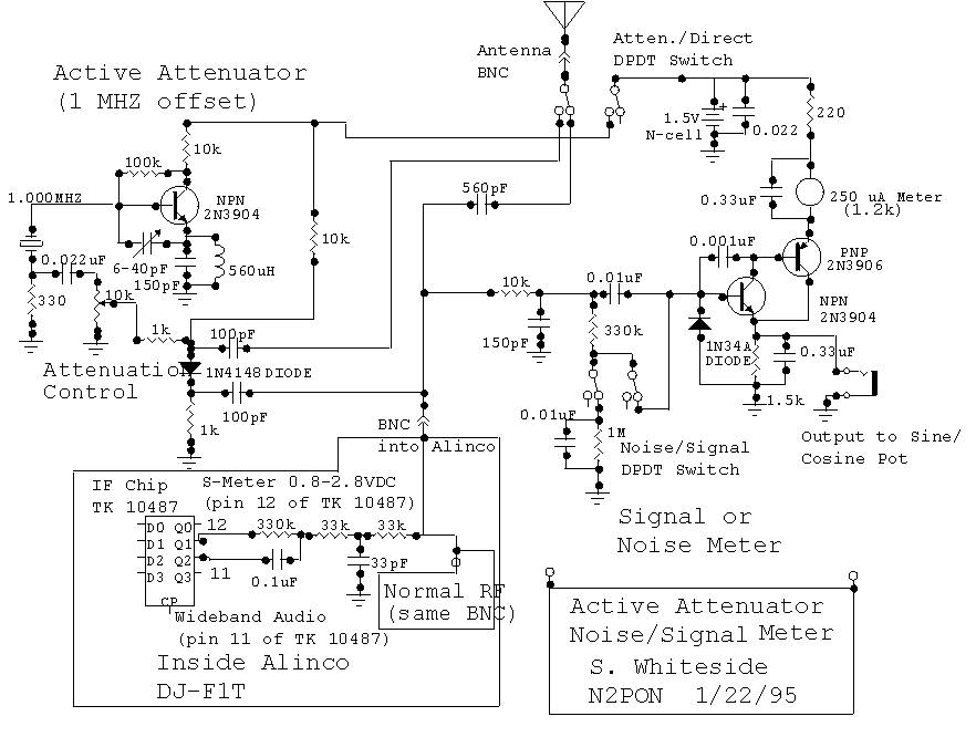
Here's a very interesting design by Steve Whiteside, N2PON for a combination Active Attenuator, External S-meter, and Noise Meter,all of which he's interfaced to his Alinco DJ-F1T HT through the single BNC coaxial connector of the HT!
While Steve's circuit cleverly sends all signals to and from the receiver on the same single coax connection, it can easily be adapted to use separate connections for the incoming RF signal (either straight through or offset by 1 MHz and variably attenuated), the DC voltage for the outboard S-meter, and the wide band audio for the Noise meter. If you don't need all the functionality that this design has to offer, just build the portion that interests you.
Steve has graciously contributed
his design to our "Things To Build" section, and is making it available
for any Amateur to duplicate for personal, non-commercial, use.
Here are some of Steve's comments.
Another nice feature is that the 1 MHz oscillator only draws 160 microamps and the S-meter typically draws 130 microamps at mid scale. So I replace the battery about once a year, as long as I remember to set the switch to Direct when not in use. With no drive from the receiver, there is no leakage through the S-meter section, so no ON/OFF switch is needed.
It is fine with me if anyone wants to duplicate the circuit for their own use. They have to get inside of their HT and solder to the parts. [Unless you're building just the active attenuator portion, in which case you can simply run the output of the attenuator into the antenna jack of your receiver. Ed.] It requires a little care. I have accidentally transmitted through the attenuator without damaging anything, but I would not recommend it. And I don't know how the switches were set when I did that.
My box is 2.125 x 3.25 x 1 inches. It was originally deeper than the 1, but I trimmed it down. The meter face is 1 7/16 by 7/8 approximately.
The 1 MHz oscillator produces 20 millivolts peak at the top of the 330 ohm resistor and that becomes 10 mV peak at the diode. The start of attenuation is about -30 dB and increases from there. I don't know what the maximum attenuation is. I normally can hunt to within a few feet of our 1.5 watt fox. -- Steve, N2PON."
How can we use this design in Fox Hunting? Well, as you get closer to a strong signal, in addition to the rf signal passing through your antenna, going down your coax (possibly through an in-line resistive attenuator) into your receiver, more and more of the strong rf bypasses your antenna and coax, and passes directly through the body of the receiver. Unless your receiver is exceptionally well shielded, soon you're receiving so much through its body that the signal seems equally strong no matter where you point the antenna. What can we do? Use an Active Attenuator.
Active attenuators work by mixing the incoming RF signal (from a hidden transmitter on 146.565 MHz, for example) with a signal from a built-in local oscillator (in this case 1 MHz), to produce several useful new signals. One is at a frequency that is the SUM of the original frequency and the oscillator frequency, and another is at the DIFFERENCE between the two. If, for example, the incoming signal were at 146.565 MHz, after mixing with the oscillator one signal would be at 146.565 + 1.0 = 147.565 MHz, and another would be at 146.565 - 1.0 = 145.565 MHz. The strength of the two signals depend upon both the strength of the incoming (hidden transmitter) signal as well as the strength of the oscillator signal, which we can easily vary by adjusting the 10K potentiometer (the Attenuation control). If we tune our receiver to one of these new frequencies rather than to the frequency of the hidden transmitter itself, we'll see that as we get closer to the transmitter we can keep our receiver's S-meter reading within range by rotating the Attenuation control and reducing the oscillator's strength. And since we're no longer tuned to the actual frequency of the hidden transmitter, we're no longer affected by the strong original signal that passes directly into the body of the receiver, so our directional antenna again works as expected.
The external S-meter in this circuit provides a remote indication of signal strength. The Noise meter is useful in hunting very weak signals. It shows the "quieting" (reduction in noise) that results as an antenna is pointed in the direction of the weak signal. In this schematic Steve has arranged to have the single meter play a dual role, remote S-meter and noise meter, depending on the position of the "Noise/Signal" DPDT switch.
[HINT: If you'd like to print
out this schematic, set your printer for "landscape" mode and then print
the frame. This way the entire schematic should fit on one page.]