Rock Mite VXO Mods
By Wayne NB6M
Copyright 2002
Download as MSWord Document (in ZIP file format)
(right click link and choose "Save As")
The results from recent experiments with VXOs indicated that, with the additions of a few parts and changes in others, the tuning range of both the 40 Meter and 20 Meter versions of the Rock Mite could be significantly improved.
The changes needed would involve removing the crystal from the input of the receiver, replacing it with simple tuned circuits, placing the removed crystal in parallel with the crystal already in the oscillator, and adding a few parts to provide for tuning the VXO.
The changes outlined below for the Rock-Mite 40 have produced a tuning range of 24.5 KHz, covering 7016 to 7040.5 KHz. Stations contacted have given very good reports on signal quality, no chirp or drift heard.
Although it is relatively easy to pull a dual crystal VXO some distance in frequency from the actual crystal frequency, the difficulty lies in designing a TX/RX frequency offset scheme that will provide a usable amount of offset throughout the entire frequency range.
This is because the amount of pulling �force� needed in order to shift the oscillator frequency enough to produce an audible tone varies tremendously. A much larger amount of pulling �force� is needed as the oscillator is tuned closer and closer to the actual crystal frequency.
Because of this fact, a normal RIT circuit cannot provide a usable amount of offset over the entire tuning range of this VXO.
In the case of the Rock-Mite, the problem is complicated even further by the fact that the oscillator frequency is pulled on transmit, and the effect is greater the further the oscillator is tuned away from the actual crystal frequency.
What that means, as a practical matter, is that the pulling effect adds to our offset when we have the �switch� mode selected so that we listen to stations above us in frequency, and subtracts from our offset when we listen to stations below us in frequency.
The VXO is tuned over a wide frequency range by progressively adding inductance in series between a pair of 7.040 MHz crystals and the tuning diode. In order to cover the entire frequency range described above, using these crystals, four tuning steps are required.
After much experimentation, a two-stage capacitive offset circuit, with selected capacitor values, was added to the VXO in order to provide a usable amount of Tx/Rx offset over the entire, four step tuning range. A single offset capacitor is used on the lower two tuning ranges, and a SPST switch places a second capacitor in the circuit for the two upper tuning ranges.
In this scheme, Q2, controlled by the keyer chip just as it is in the stock Rock-Mite, switches the offset capacitor or capacitors into and out of the circuit.
Because of the non-linearity of the effect of the offset capacitor over the wide tuning range of the VXO, the reception tone will not be the same throughout. On the lowest tuning range, from 7016 to 7031 KHz, the reception tone will vary a considerable amount from one end of the tuning dial to the other. This effect is not as great on the upper three tuning ranges, from 7031 through 7040.5 KHz.
However, it is very easy to �spot� the transmitting frequency by means of the �switch� mode built into the keyer chip. The push-button is used to change frequencies, the Tune control is adjusted to zero beat the received station, and the push-button is used again to return to the receiving frequency.
Here is the schematic of the Modified Rock-Mite 40 VXO:
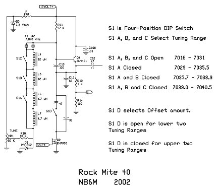
Coverage from 7016 through 7040.5 KHz is accomplished by selecting four tuning ranges in turn, by progressively closing S1 A, B, and C. S1 D is left open for the lower two tuning ranges, and is closed for the upper two. The lowest tuning range is selected when all switches are open.
Closing S1 D adds a 47 pf cap in series with the 33 pf offset capacitor that is used on the two lower tuning ranges, in order to produce enough of an offset on the two higher tuning ranges.
TX/RX offset is accomplished by the action of Q2, either grounding or un- grounding the offset capacitance, effectively placing it in parallel with C11 for transmit or removing it, depending on the state of the �switch� mode selected by the keyer control button.
Because of the non-linearity of the amount of frequency offset provided, the reception tone should be somewhere between about 600 Hz and 1000 Hz, depending on the tuning range selected and the area of that tuning range the VXO is tuned to.
Also, the oscillator�s output is reduced somewhat when the offset capacitance is in parallel with C11. This does not affect the receiver, but does lower the output of the transmitter.
The modified Rock-Mite 40 in use here has had its PA transistor changed to a 2N3053 and R 18 shorted across.
With the offset capacitance in parallel with C11, the transmitter output is 500 mW at its lowest, which is the low end of the lowest tuning range, where the oscillator is pulled the furthest away from the crystal frequency.
The effect is not so large on the upper tuning ranges, and over a Watt of output results.
However, if one selects the �switch� state where the offset capacitor is in parallel with C11 on receive, and is removed by Q2 on transmit, over a Watt of output will be had over the entire tuning range.
DOING THE MOD
To get started on the mod, remove Y1 from the board. It will be installed in parallel with Y2.
Remove R10, R9, and C10. Replace C10 with a 100 pf NP0 cap.
Next, on the top of the board, cut the trace that runs from the right hand pad for D5 to the now empty pad just to the right of Q2. Cut it just to the left of the printed �D� in D5 on the top of the board. Replace R9 with a 270 Ohm resistor.
Install the 270 Ohm resistor so that the body of the resistor is on the right and the bare lead is on the left, as you look down on the board from the front. Solder the bared end of a 3 inch length of hookup wire to the bare lead of the 270 Ohm resistor. This lead will be connected to the top of the Tune Pot in order to supply 7.5 Volts regulated, taken from D5, to the VXO�s tuning circuit.
Solder the bared end of a three inch length of insulated hookup wire into the right hand pad for the removed Rock-Mite R10. This will be connected to the bottom end of the diode across S1 A, as shown in the schematic.
Next, on the bottom of the board, cut the trace that runs between the pad for the top end of D6, the tuning diode, and the pad for Y2 that is directly even with D6 on the board.
This is done so that the inductors and corresponding wiring can be installed in order to broaden the tuning range of the VXO.
The trace between the pad for the top of D6 and its corresponding pad for Y2 is the only trace on the bottom of the board that needs to be cut in order to implement the changes in the VXO.
As the ground plane extends right to the edge of the bottom of the board, carefully file just the ground plane back about a 16th of an inch from the edge, even with Y2, so that the crystal removed from Y1�s spot can be installed in parallel with Y2 without inadvertently grounding its contacts.
Rest the �Lip� of the crystal on the top of the board, with the two crystals parallel and touching and the two wires extending from the bottom of the second crystal running right alongside the edge of the board. Solder their tops together, and then use two short lengths of cut off part lead to wire the two crystals in parallel.
The inductors I added to the circuit were surface mount parts, but molded RF chokes can be used as well.
In initial experiments with the Rock-Mite VXO, I installed the inductors on the bottom of the board, between the pad for the top of the tuning diode and the pad for Y2 that is even with D6 on the board. I ran short lengths of hookup wire from each inductor junction to the switch I used to select them. Three 12 uH inductors, installed in series in that location, gave a tuning range of from 7018 to 7040.5 KHz.
When I installed the three inductors on the rear of the DIP switch indicated in the schematic, the VXO tuned all the way down to 7005 KHz. However, the transmitter�s output was very chirpy. I reduced the third inductance to 9.4 uH, by using two 4.7 uH in series in place of the third 12 uH coil. This resulted in the present tuning range, down to 7016 KHz, with a stable transmitter output.
The pair of 4.7 uH coils in series go between the contacts of S1A. The two 12 uH coils go between the contacts of S1 B and C. Use short pieces of cut off part lead to connect the upper contacts of S1A and S1 B, and the lower contacts of S1 B and S1 C.
With S1 A, B, and C all open, the three inductors should be in series between the dual crystals and the tuning diode.
The wire previously installed in the right hand pad of the Rock-Mite R10 is connected to the lower contact of S1 A, which has the lower end of the third inductor connected to it. A 10 K resistor will connect from this same contact of S1 A to the wiper of the Tune Pot.
Connect the wire coming from the bare lead of the installed 270 Ohm resistor to the top contact of the Tune Pot, and connect the bottom contact of the Tune Pot to ground.
Solder another short length of hookup wire between the junction of the paralleled crystals that is directly even with D6 on the bottom of the board and the upper contact of S1C, which has the upper end of the first diode, as shown in the schematic, connected to it.
Solder one lead from each of the two offset capacitors to the right hand pad for C11, on top of the board. This is the contact of C11 that connects to the emitter of Q4. The remaining loose leads of the capacitors go to the two contacts of S1 D, one to one contact and one to the other.
Solder a short length of hookup wire between the empty pad next to the drain of Q2 and the S1 contact that the 33 pf capacitor is connected to.
That completes the VXO portion of the Mod.
Here are the changes to the receiver input:
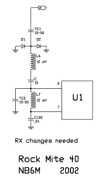
In this case, Y1 has already been removed from the board, and now C1 and C2 are removed. A 15-50 pf trimmer, TC1, replaces C1.
There is a small discrepancy between the Rock-Mite circuit diagram and the actual board connections. The circuit diagram shows C1 coming off the output side of C14, but C1 is actually connected to the Collector of Q6 on the board.
This makes no difference in reception, except that I did not get quite as sharp a peak when I tuned TC1 as I should have. I believe this is due to the capacitance felt on the collector of Q6. Either the TC1 pick-off point should be connected to the output side of C14, or different capacitor values experimented with in order to truly resonate TC1 and L6 in my drawing.
A 12 uH RF choke and a 15 pf cap in series, as shown in the drawing, replace Y1. Be sure to connect the two so that the 15 pf cap connects to pin 2 of U1.
Even without a sharp peak in TC1�s tuning, the receiver is quite sensitive, and I highly recommend that an RF gain pot be installed between the junction of L6 in the drawing and the 15 pf cap. Either a 1 K , 5 K , or 10 K Pot should work fine. I wired the earphone jack so that the individual earpieces are in series and on strong signals the audio is quite loud, so be careful.
L7 replaces C2, and TC2 is connected from the pin 2 (of U1) end of L7 to ground. It might be necessary to mount this trimmer, or most of the RX input circuit, either on a nearby surface of a PC board case, or on a separate, small, piece of PC board. Use your imagination and adapt its installation to your own individual configuration.
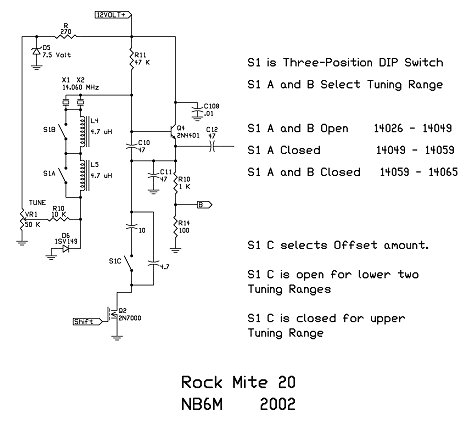
ROCK-MITE 20 VXO MOD
I have not yet �Modded� a Rock-Mite 20. However, the successful conversion of the 40 Meter version, coupled with experiments made on a bread-boarded RM20 oscillator, indicate that an even wider tuning range is possible on 20 Meters.
The Mod would be implemented in exactly the same way.
Here is the schematic, including proposed values for the offset capacitors. Some experimentation may be necessary to fix their values in the actual RM20.
Here is the schematic of changes to the 20 Meter Rock Mite�s receiver input:
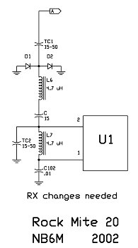
Follow the same basic instructions outlined above for modifying the Rock-Mite 40 to make these changes.
FINAL THOUGHTS
It has been interesting learning how effective the switching of a series of inductors in and out of a dual crystal VXO circuit is in producing a wide tuning range. Also interesting is that the oscillator works differently when individual inductance values are added together than it does when a single inductor of the total value is used.
The wide range VXO seems to �like� multiple inductors added together much better than the single inductor of the total value, resulting in a wider tuning range with higher output voltage levels.
One side note is that, when multiple inductors are used, there is a definite benefit in mounting the inductors directly on the back of the selector switch. That keeps the �leads� from the inductors to the switch quite short.
What I learned in my experiments is that if the inductors were mounted separately from the switch and wire leads used to connect them to the switch, there were gaps between the coverage of the individual tuning ranges, caused by the small amount of reactance introduced by the leads. This was especially true in the 20 Meter VXO.
Depending on the physical layout of the individual installation, some experimentation in the actual values of total inductance will be needed in order to achieve both the tuning range desired and a stable transmitter output over the entire tuning range.
Some experimentation may also be needed with the values used in the two offset capacitors, in order to realize a usable amount of Tx/Rx offset throughout the entire tuning range.
Although the tuning range of the modified RM40 is less than that of the modified RM20, the results are very gratifying. In both cases the mod is well worth it in terms of changing a single frequency transceiver into one that has a very useful amount of frequency agility.
It is important to realize that, while the results you get from applying the same exact mod to your own Rock-Mite may vary slightly, those variations can be compensated for by small changes in either the amount of inductance used or the values of the two offset capacitors.
Further experiments are being conducted in efforts to improve the TX/RX offset scheme and to improve the linearity of the oscillator�s output in terms of drive supplied to the transmitter. In the meantime, these �Mods� make a neat little transceiver even more fun and useful.
As with all of the previous �Mods� I have developed, this one is a continuing work. I expect to continue to refine it, and hope that, with the sharing of the results they produce on other Rock-Mites, we can all benefit in terms of improving both the circuits themselves and our understanding of how they work.
Enjoy.
Wayne NB6M copyright 2002