80
METER LOADED VERTICAL
I used a dipole on 80 meters which was 50 feet high. I found it quite useful for working Europe but not very successful at working long distance DX. This was due to the low height of the antenna which was less than 0.5 l.which tends to make the take off angle high, since most Dx comes at a low angle. This was confirmed by using aerial analysis software called NEC4WIN95VM I then turned the dipole into an inverted V this gave me some vertical content to my radiation pattern. This did not lower the take off angle any further.
The importance of take off Angle:
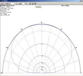
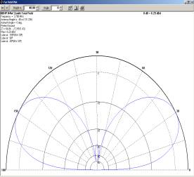
Figure 1 Figure 1a
If you look at the two patterns shown in the above diagrams Figure 1 and Figure 1a.
Figure 1 shows the antenna has a high radiation angle and Figure 1a shows a low radiation angle. Most people who have played snooker , billiards or pool , will know that when a ball is hit onto the cushion it always returns at the same angle as it struck the cushion. If you can imagine the cue ball as the radio wave and the cushion as the ionosphere this is what radio waves do when they hit the ionosphere. The return angle is the same angle that hit the ionosphere. The take off angle is very high . The return angle is also very high it returns back to ground having not travelled very far horizontally in distance.

Triangle P, Q, R are the same as Triangle R, Q, S So angles A1+A2+90=180 Also A4+A3+90=180
So angle A1=A4 And A2 =A3 Distance travelled =d1+d2 but the Distance travelled =2*H*Cos(a1)
If the take off angle is very low the radio wave hits the ionosphere and comes off at a very low angle but travels further than the high angle signal horizontally. You will also note that the height of the ionosphere has an effect on the distance travelled horizontally . I have worked out with some simple maths using trigometry to explain the basic principles of what I am describing. We also need to remember that the radio wave has a ground and also a sky wave . The ionosphere effects the sky wave only. This model is a very simple model and describes only the basic principles of what happens. Of course in nature there are other effects which can take place.
.
The Vertical
The aerial that gives you a low radiation angle is a
vertical which consists of a 0.25 l.
Rod and some radials which are 0.25 l. long See Figure 3
To find 0.25 l at 3.65Mhz ( Centre of 80 meters band )
l( in meters ) =C/f
When C is speed of light 3* 108 meters per second
When f in Herz
so l=3*
108/3.65*10^6
l= 82.1917 Meters
0.25 l=20.5479 Meters
Since radio waves are not travelling in a vacuum but through a metal rod ( or wire )
the radio travels at 0.95 of C .
so 0.25 l=20.5479 *0.95 Meters
0.25 l =19.5205 Meters
For those people still using feet and inches
If you use the above formula and convert metres to feet ,and still use velocity factor of 0.95 it simplifies to 0.5l =468/ f where 0.5 l in feet snd f in Mhz (from ARRL HandBook )
0.5l ( feet) =468/3.65
0.5l =128.21917 feet
0.25l=64.11 feet
This is very long for the vertical rod ,however you can use a shortened rod ( <0.25 l) by using an inductor to make the aerial resonant at 80 metres ( since a shortened vertical is capacitive R-Jx )
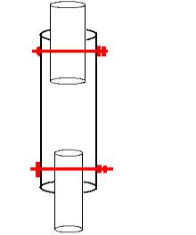
The inductor could be located in the aerial base, or higher up from the aerial base. If you go above the base you
would require an additional length of rod above the inductor. There is a current flowing through the aerial which is dependent on any given position along the aerial. This current is equal to IP=IM COS(2 p L/l)

Figure 4
Where IP is current at any position along the aerial and IM is the current at the base, and “L” equals the distance along the aerial l is the wavelength. The current at the base is equal to IM, since the current is flowing through the inductor. Where the inductor is at base position, the RF resistance of the inductance will dissipate RF Power as heat, and is subsequently lost. Any inductor wound on a former will have resistance due to the wire used for winding. These losses are I2R whilst you cannot eliminate them, the losses can be minimised. It is important to realise that the DC resistance of the wire is not the same as the RF resistance. This is due to the skin affect. The RF resistance can be many times larger than the DC resistance and depends on the operating frequency.
Building the Vertical
The vertical is made up of a number of aluminium tubes of various diameters. I purchased from the local metal
Merchant a twenty foot aluminium scaffold pole with a diameter of two inches. I also was given eleven foot
Off cut. These were joined together using an aluminium pipe joiner which made the base of the antenna. I found a solid bakelite rod, two inches in diameter which would make an ideal former for winding the loading
inductor on . I drilled a hole in one end of the bakelite rod approximately three inches in depth, diameter of 1.75 inches and the other end had a diameter of 1.5 inches with the same depth of 3 inches. I found one piece of 1.75 diameter aluminium tubing which was 18 inches in length ,and another piece which was 1.5 in diameter and 51 inches long. I fitted the rod at each end drilling a hole through the former at each end to hold the rods in place. At a later date these bolts will be used to make connections to the inductor. Wind turns on the bakelite former to make the inductor. Secure the connection by winding the bare end around the bolt and tightening the nut to lock the wire in place. For the inductor use a heavy gage wire SWG10 or SWG 12. The value of inductance you need is 19.1uH .This is done by winding some turns on the former and measuring the inductance with a bridge By adding or subtracting turns to give the correct inductance the mathematical method I use is L (uH) =N2/S where L is inductance in Microhenry and N is the number of turns and S is the reluctance of the core. To calculate S just wind some turns on the former and rearrange the formula to obtain the value of S since the number of turns and inductance is known. Now that the value of S is known and the inductance you require you can calculate the value of N2 . By finding the square root you can find the value of N and then wind the number of N turns on the former this should give you the approximate inductance you require. To fasten the coil to the 2 inch pole, the end of the coil which has the 1 ¾ inch tube at the end goes into the 2 inch pole with a bolt driven through both You may need two bolts to make it firm, the other end could be connected to the Sigma aerial by putting vertical slits into the 1 ½ tube and fitting the sigma aerial inside the same tube with a jubilee clip to secure it in place.. simple dx verical can be made for cheapler and if well thought out can give good results
I calculated the inductance of the inductor to be 19.1uH. This value was worked out by using the aerial analysis program called . NEC4WIN95VM. The whip above the inductor was made from a CB half wave sigma antenna. The total length of the aerial was 45 ft 9 inches. This was mounted on to the side of the house with three strong wall brackets. The bottom of the antenna consists of a water proof box, which made the connection to the PL259 plug with some radials also connected to the antenna. The bottom of the aerial is approximately nine feet from the ground. The antenna is guyed with three guys 120 degrees apart, because of the high winds we have in the winter. I have included a table of all the aluminium lengths and diameters.
|
Aluminium
tubes In Feet |
Diameter
in Inches |
|
10.9166 |
2 |
|
19.666 |
2 |
|
4 |
1.5 |
|
4 |
1 |
|
2.5 |
0.875 |
|
1.5 |
0.75 |
|
1.916 |
0.625 |
|
1.166 |
0.5 |
|
|
|
|
Total
= "45.666 Feet |
|
|
|
|
Radials
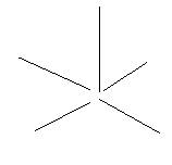
The radial system is important as this determines how well the aerial functions. Firstly I attached four 0.25l radials these were bent to fit the space available. I added also some shortened radials these lengths were
From 0.1l – 0.2l . After having both the 4* 0.25 l and the shortened radials which consisted of about 60 shortened radials I noticed an improvement to the Dx signals . After this I added some raised radials in a fan pattern . These radials were shorter than 0.25l but raised at one end with the other end at a lower height. This made a large improvement on signal strengths. The raised radials seemed to lower the take off angle of the antenna and improve its efficiency. I noticed 1-2 S point and sometimes even 3-4 on certain directions. I found that I could work some Dx which normally I could not work with the dipole. I managed also to work a couple of VKs. , ZL , North and South America
![]()
![]()