
17 Metres And 12 Metres
Beam.
INTRODUCTION
For some years I used an X7 antenna made by Cushcraft operating on 10, 15 and 20 Meters. This aerial is basically three mono banders on the same boom. The driven elements for each driven dipole are connected by a criss cross transmission line , this makes it possible to use with a single coax. It looks similar to a log periodic with both directors and reflectors. In the technical literature the connection of the dipoles with criss cross transmission line is called a log cell giving a low SWR on 20, 15 and 10 Meters. Due to the way the dipoles are connected I found that I could use it on 18 Mhz ( 17 Metres) and 24.Mhz (12 Meters) ,whilst the gain was not very high on 18 Mhz or 24 Mhz it did give me the advantage of some directivity, on both front to side and front to back attenuation. The typical gain measured for 18.118 Mhz was between 2-3 dbs.and 24.95 Mhz and was 1.5 to 2 dbs. The gain quoted in the technical literature was 12 dbs for 10, 15 and 20 Meters.. The aerial is not really designed to be used on 18.118 Mhz and 24.95 Mhz , so a low gain figure would be expected , as the aerial is working outside it’s parameters. The use of an aerial tuner brings the SWR down from 4 - 1 to 1- 1 .5. The changes in impedance to provide a match are quite substantial, and this can be achieved by using the aerial tuner , however, whilst there were .losses using this method. it was still possible to work DX . However when I wanted to go on 10, 15, or 20 Meters I had to remember to take out the aerial tuner. This was satisfactory for a short time, but in the long term I needed an antenna for 18 Mhz which did not use an aerial tuner and would provide a higher gain than the X7 with the aerial tuner.
HISTORY
The aerial began as
an 17 meters aerial with high gain, but
the front to back ratio was poor
only - 15 dbs Then I started
to work on 12 meters but when we had a high sun spot count I
found by
using my X7 and ATU it worked on 12
meters although very poorly. My best DX on 12 meters was a station in the
Indian Ocean but
I did not get a good radio report from him only 5/2..
I increased the number of elements to 6 in total..This gave 3 elements on 17
meters
and 3 elements on 12 meters
This worked well as it
opened up both 17 and 12 meters for me, but the
front to back ratio was
still only -16 to -17 dbs not satisfactory.
In February of 2008 after a
storm the
aerial did not survive and suffered some slight damage to x7 and
broke the extension pole from the top of x 7 and the 17/12 meters beam.
It snapped the boom of 17/12 meters beam and bent some elements
I decided to rebuild the
aerial so I used the aerial
software from which I used to make the original aerial.
I wanted to get the gain on 17 and 12 meters to the same value but most
important was improving the front to back ratio ..After a number of hours on the
computer it gave a gain on
17 meters 5,67 db and front to back ratio –20 db
and for 12 meters the gain was 6.31 and
front back ratio was –29db.
This was modeled in free
space. When I modeled with a
real ground which uses 13
dielectric constant and 5 for conductivity (mS/m) this suited the local
conditions giving a gain on 17
meters of 11 db and front back ratio of –20 db. For
12 meters the gain was 11db
and front back ratio was –30 db. I
tested it on 17 meters with my
friend Angelo W8ERN. We tested the front to back ratio of the antenna
and it was 5/9 + 20 in a forward direction. .On the back of the
aerial he was barely audible. I was unable to test the aerial on 12 meters
because the conditions were unfavourable. However I am confident that the
software is correct giving me a high front to back ratio This
was a positive improvement
on front to back ratio and the gain.
The price of a 17 metres or 12 metres Beam or 2 band beam ( Cushclaft A3WS ) to achieve the result I wanted was too costly ,I therefore decided to design my own. I based my design on using 12 sigma half wave CB antenna ( 27Mhz). The 12 sigma’s were purchased from CPC part number AP00540 and it comes with telescopic aluminium tubing, jubilee clips and U clamps.. This provides all the materials necessary to build the elements, fortunately I had available some 2 * 1“ box section in 3.96 Metres (13 feet ) lengths Two pieces were needed to make the boom 6.4 Metres (21 feet ) long., one piece 3.96 Metres (13 feet ) long the other piece 2.44 Metres (8 feet ) long.. If the box section is not available you could use 2 pieces of aluminium tubing with a diametres of 50 mm (2”), this could be supplied from a TV aerial rigger or aluminium supplier. When using aluminium tubing or box section you can join the two pieces together by inserting several pieces of smaller bore tubing 1000mm (3 feet) long down the centre of one of the sections making sure that there is at least 500mm (18 inches) of aluminium tubing down the centre and protruding out. Make sure that the tubing is inserted tightly and then gently tap the other tubing so that it slots in to place , completing the full length boom and bolting through to hold the two together using 4 bolts so that there are two bolts to hold one half of the boom and two bolts to hold the second half. If you make the bolts so that they go through the boom in different planes of origin ie the first bolt runs North South the second bolt runs East West and the third bolt North South and the last is East West as in the diagram shown below. Joining the aluminium as shown in the diagram is to keep any stress on the join to a minimum. . When using aluminium tube to strengthen the joint, fit an aluminium pipe joiner or use another piece of tube which is 24 inches ( 60 cm ) long and has a inside diametres of the same size as the outside diametres of the boom so that they can slide inside each other using the bolt method as described above. I found that this was the best method to give a very strong joint. When using box section instead of using the pipe joiner, four pieces, of aluminium sheet/ plate are cut to cover the four sides of the box section about 500mm (18 inches) ,they can then be bolted evenly across the joint on. the boom.
CONSTRUCTING
THE ELEMENTS.
Now the boom is assembled the next step is to assemble the elements.. First totally dismantle twelve sigma half wave CB antenna ,. then remove the telescopic aluminium tubing.
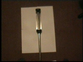
Remove screw releasing top black plastic cap.
Remove three grub screws from base releasing bottom black plastic cap
and aluminium tube.
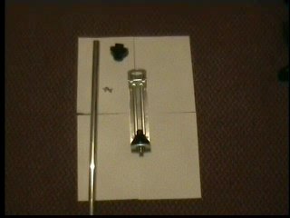
Carefully remove the coil in the bottom black cap
This completes total dismantling of the twelve sigmas.
Remember to keep all the loose pieces as some of them will be used to make the antenna.
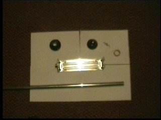
Using a hacksaw cut off the two sides on six aluminium base plates
leaving four flat base plates each with four holes for U bolts.
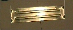
Remove the top flaps from the two base plate, keeping the flap with the S0239 socket mounted on it, this will be used to connect your coax to the antenna.
The aerial has two driven elements, one for 17 and the other for 12 metres
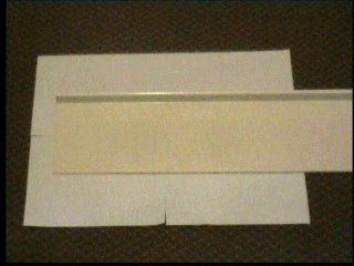
I obtained from a local builder a piece of plastic window sill. I cut 4 pieces of plastic to match 4 of the flat aluminium plates and drilled through the holes in each corner. With the other two aluminium plates I repeated the exercise but made the plastic plate three inches wider than the aluminium plate on one side.(Perspex could be an alternative to plastic providing you use a thick gauge.). I then obtained from a builders merchant a piece of 40mm (1.5 inch ) diametres water hose pipe, and four plastic central heating wall pipe holders as displayed.. The plastic wall clamps are to hold 6mm (0.25 inches) aluminium tube pipe used in the assembly of the gamma match to the wider side of the plastic base on the drivers .
THE PLASTIC/ PERSPEX PLATE MUST BE FITTED UNDER THE ALUMINIUM PLATE.


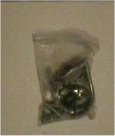
Each of the sigma half wave antenna’s includes a small bag containing jubilee clips, nuts and bolts and U bolts. This will be used to construct the elements.
|
|
|
|
17
& 12 |
Metres |
Beam |
|
|
Diametres |
|
|
ele1 |
ele2 |
ele3
|
ele4
|
ele5 |
ele6 |
|
|
|
|
39.5 |
30 |
32.5 |
38.5 |
26 |
31.5 |
|
0.5 |
|
|
39 |
29 |
27 |
39 |
24 |
39 |
|
0.625 |
|
|
39 |
20 |
16 |
39 |
20 |
39 |
|
0.75 |
|
|
25.5 |
20 |
20 |
19.5 |
20 |
19.5 |
|
0.825 |
|
|
22 |
22 |
22 |
22 |
22 |
22 |
|
1 |
|
|
22 |
22 |
22 |
22 |
22 |
22 |
|
1 |
|
|
25.5 |
20 |
20 |
19.5 |
20 |
19.5 |
|
0.825 |
|
|
39 |
20 |
16 |
39 |
20 |
39 |
|
0.75 |
|
|
39 |
29 |
27 |
39 |
24 |
39 |
|
0.625 |
|
|
39.5 |
30 |
32.5 |
38.5 |
26 |
31.5 |
|
0.5 |
|
|
|
|
|
|
|
|
|
|
|
Total |
330 |
242 |
235 |
316 |
224 |
302 |
|
|
|
|
|
|
|
|
|
|
|
|
|
Spacing |
0 |
10 |
105 |
135 |
195 |
240 |
|
|
All element sizes are in inches. The total length of the elements is from one end to the other. Also please note that the 1 inch tube is 44 “ long and it saddles the mid point of the boom. The feed points for the twelve metres driven element is coloured red on the table and the driven element for 17 metres is coloured blue on the table.
Cut twelve pieces of 40mm.(1.5 inches ) outside diametres (inside diametres 31 mm 1.25 inches) water hose pipe 75mm( 3inches) long to use as insulators between the element , aluminium plate and U bolt Take each element marking the centres with a felt pen. Repeat process on the aluminium plates. Thread two pieces of water pipe on each of the elements. Align the two centres and put the plastic / perspex insulation plate underneath the metal plate. Put the two U bolts into the holes in the base and through the plastic insulator making sure that the plastic pipe is between the element and U bolt. The plastic insulator will insulate the aluminium base from the boom. There has to be a connection made between the centre of the element and the plate. This is done either by putting a piece of aluminium or a metal nut centrally between the element and the aluminium plate, tighten the U bolts down this will hold all component parts in place. See below: This is the method used for mounting all the elements on to the base. The driven elements are slightly different, after fitting insulation you have to slide the additional base with the SO239 between the base you are mounting the element on , and the tube. Some holes need to be drilled to enable U bolts to be used to mount the element on to the boom .The small U bolts supplied with the sigma half wave CB antenna ( 27Mhz) can be used to hold the element to the aluminium plate and plastic insulator. A heavier duty U bolt should be used to hold the element to the boom ( car exhaust clamps in various sizes are available)

DRIVEN ELEMENT
CONSTRUCTION

Fix the elements on to the boom as shown making sure that the elements are in the correct
positions. The next item to add is the matching unit. I have used a gamma match as this is very robust. A piece of aluminium tubing is required about 6mm (0.25 inches ) diametres for the gamma a match, about 1.117 metres (42 inches) long.

The gamma match rod has to be 50 mm ( 2 inches) from centre to centre of the driven element. It may be necessary to put it slightly left or right of the centre of the plate holding the socket, possibly about 25mm (1inch) this will not make any difference to the impedance. To fit the gamma matching rod to the wider
plastic / perspex base on the driven element, I used plastic C/H. water pipe clamps with a central hole for bolting to the plastic / perspex base. Electrical tape around the pipe will ensure a tight fit . With the gamma match a capacitor is needed which is in series with the rod and this is connected to the SO239 socket ( centre pin) this capacitor is used to tune out any inductive reactance which the gamma match produces. This value is 100 pf, this can be made up of fixed capacitors and be located into the original black cap that covers the socket arrangement. Put a bolt through the hole where the original grub screw held the element to the black cap and take a wire from the screw to the gamma matching rod. The shorting bar from the gamma match to the driven element is about 37 inches from the driven end. Since some of us run 400w pep on 17 Metres the voltage across the capacitors has a very high value.(the capacitor must have a working value of 1000v and should be of high quality mica) It may be a problem trying to get capacitors with high enough working voltage of a suitable size to fit in the black cap. Another method explained to me by a W4 was to use a piece of UR67 coax. Cut a length and thread it down the centre of the gamma match rod and join the inner to the outer braid, still keeping the thick black plastic covering on the coax. (I found 14 inches ( 355 mm ) of UR67 coax will give the correct value) This will form a capacitor between the rod and the braid. The black plastic cover is used as the dialectric. Use a capacitance bridge to obtain the value of 100pf. It may be necessary to trim the coax to size to get the correct value. I personally dab a small piece of glue from a glue gun on the ends, this stops the possibility of shorting on to the gamma rod. The next step is to add the elements as in the Table above checking that the overall distance between the centre and the far end are as shown in the Table

TUNING UP:
Set the gamma match to the value as stated above, although you may find you have to change the position of the rod that shorts the gamma match to both the driven element and to the value of the gamma match capacitance. I have set this so that the resonant frequency of the aerial is at 18.118Mhz for 17 metres and 24.940Mhz for 12 metres this will give you a low SWR over the whole of the 17 and 12 metres bands. If you can put the aerial so that element 1 is sitting on the floor and pointing straight up this is the better way of making any changes to the matching. As shown above the plate for mounting the
Boom to your pole is positioned just before the join ( DO NOT POSITION THE PLATE OVER THE JOIN AS THIS PUTS A LOT OF STRESS ON THE JOIN) I use this at several different heights ranging from (10 22 Metres) 30-70 feet and the aerial performed very well. I measured the gain to be 10Dbs and managed to work a lot more DX. I noticed I had greatly better front to back ratio than before. What was also noticeable however was the increase in gain. I have already worked Ws on the East and West Coast ,VU2, VK and ZL, and some stations in the Indian Ocean, Zanzibar . VP6 in Pitcairn Islands and ZS.
![]()
![]()