12 VOLT 20 AMPS POWER SUPPLY
One day a friend of mine came to visit me who was an Mi6 and he asked me to look at his power supply as he said there was a lot of hum on it. The output voltage was not 13.8 volts when I put a load on to it ( I used a resistor which draws about 4 amps from the supply ). When I looked at the regulator transistors they were ok but the smoothing capacitors were leaking electrolytes out of the top vents and the regulator board was not working. I gave him a computer power supply for an old PC these can give 12v ,5v and -5v and 3.3v. These power supplies are regulated and protected against current and voltage over load ( line voltage does do > v out ) You can run most rigs on 12v since they can be connected to a 12v car battery and work ok. You will notice a slight power reduction on transmit ( 15% reduction in power output )A few days later he came back on air and said that he was pleased with the power supply and was told that audio on his tx was a lot better than before . He told me to keep the old power supply and use it for bits. I decided to rebuild the power supply. I got rid of 2 electrolytic capacitors as they were of no use and also the voltage regulator board as well. It had 4 2n3055 transistors as series regulator transistors. These transistors are connected in parallel together with resistors to make sure that the current is shared between each of the 4 transistors equally. I started to look at voltage regulated circuits and first looked at this circuit. See below.

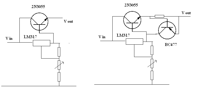
Classic voltage regulator circuit using LM317. The output voltage can be between 2v and 32 v depending upon resistor values. Current is limited to 1 amp then you could add a series transistor to boost the current up to 5-10 amps.

The first circuit uses a 2n3055 to give you more current output. This has a disadvantage that draws too much current through the 2n3055 and blows it up. The second circuit is the same as the first except that a sensing resistor in the emitter of the 2n3055 has been added. When there is 0.6 volts across this resistor it turns on BC477 that turns off the 2n3055 putting the output to zero. This will work ok but since you add a resistor in the emitter of the 2n3055 this resistor will drop voltage across it ( this will dissipate power in the resistor ) and the output voltage is reduced by the voltage drop across the resistor this reduces regulated voltage.
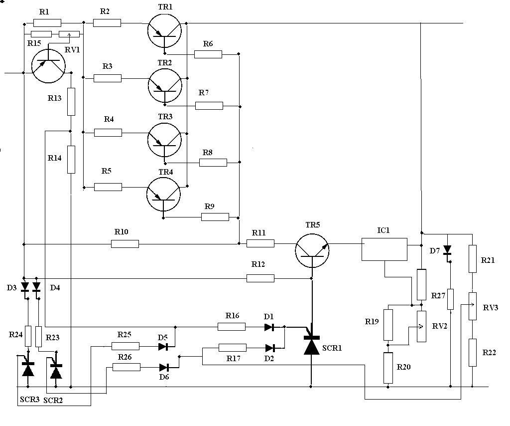
The circuit I use is LM317 and 4 transistors in parallel with resistors to make sure that the current is shared equally. Each transistor is taking 1/4 of the output current. This circuit gets over some of the problem I explained above. I have written an explanation of how the circuit works on the following link . my 12 volt 20 amp power supply.

Here is the link so that you can download power
circuit diagram. ![]()