Introduction.
When
transmitting or receiving QRSS one of the most important factors to
consider is frequency stability. Even a well designed crystal
oscillator will still exhibit "drift" to some degree. With regular 12
W.P.M. CW or voice S.S.B. a crystal oscillator would be more than
capable of maintaining the required degree of frequency
stability but for QRSS applications it may not be
sufficiently stable.
The single component which
determines the stability of a crystal oscillator more than any other is
the crystal itself. Other components which effect the stability include
any inductors or capacitors used to "trim" the crystals frequency. It
is quite common for the crystal not to oscillate at exactly the desired
frequency with the result that a small trimmer capacitor or some
inductance may be required to bring the frequency to the required
value.
The most common cause of "drift"
in any oscillator is due to the effects of temperature change on the
frequency determining components. In the case of a crystal oscillator
this is the crystal itself and any additional components used for
frequency "trimming". Inductors in particular can be very
sensitive to temperature changes. In order to achieve the highest possible
stability of the oscillator a number of factors should be
observed.
The oscillator should be Solidly Constructed with all the components securely mounted and with short component leads. Secondly, the oscillator should have a Stable Power Supply
and preferably be from a "low noise" source. Some three terminal
Voltage regulators can be very "noisy" which in turn leads to amplitude
and/or phase modulation of the oscillator. Thirdly, the oscillator
should be maintained at a Constant Temperature.
One solution to maintaining both
short and long term frequency stability is to phase lock the crystal
oscillator to a stable
frequency standard, this usually takes the form of a G.P.S. disciplined
crystal oscillator which effectively makes the crystal oscillator as
stable as the atomic clock to which it is referenced. For many this
level of complexity or additional cost may not be acceptable in
which case the next best thing is an oven controlled crystal
oscillator or O.C.X.O. The "oven" maintains the crystal at a
constant temperature and thereby ensures greater frequency stability in
the event of changes in ambient temperature outside of the oscillators
enclosure. After the initial "warm-up" period of the oven both the
temperature and the frequency stability remain much more constant
over time.
M0AYF Crystal Ovens.
Presented here are two crystal oven
designs I have found to be very successful. Both designs have been
built and tested several times to ensure repeatability and reliability.
In both cases the choice of components has been based on currently
available or easy to obtain parts. Most of the parts are not critical
and considerable latitude exists in the components chosen. Both
circuits have advantages and disadvantages but because of the
similarity between the two designs it is possible substitute elements
of one circuit into the other to suit personal requirements and achieve
the required performance.You can build these designs yourself or simply
use them as a guide for your own experiments. Both circuits have been
designed with the
following points in mind.
- Easy to obtain components (from the "junk box")
- Single supply rail (nominal 12 Volt) operation.
- Easy to set-up.
- Stable and reliable operation.
- Reproducible by others.
So here are the designs, the MK-1
is most suited to maintaining the temperature of an entire
oscillator/enclosure. As a consequence of heating the entire enclosure
the design consumes more power than would be required for simply
heating a crystal on its own. However, it offers a very high level of oscillator
stability by virtue of maintaining all the oscillator components at a
constant temperature of around 40 degrees centigrade and maintaining temperature
to better than one degree-C over time. This design is best suited to a QRSS transmitter.
The Mk-2 consumes much less power than the Mk-1 since this design is
intended to heat only the crystal and perhaps one or two additional
components in thermal contact with the crystal. This design regulates
temperature at around 30 degrees centigrade and maintains temperature
to better than one degree-C over time. This design is more suited to
QRSS receivers or to applications in which power consumption is very
important as in portable operation etc.
Important note.
Both of these designs will benefit from good thermal insulation
around the enclosure (Mk-1) or the crystal/trimming components (Mk-2)
by helping to reduce the power consumption. Thermal insulation also
shortens the
"warm-up" time of both ovens and shortens the "cycle time" (time the
oven is ON/OFF) which again reduces power consumption and gives better
temperature regulation.
Choice of oven temperature.
It is a good idea to make the temperature safely above the
ambient temperature to ensure the oven has a good safety margin for
reliable operation. For example, if you happen to live in a very warm
climate in which temperatures often reach 30 degrees-C or greater then
an oven temperature of 45 to 50C may be in order. Here in the UK we
rarely see those kind of temperatures so for the design of the Mk-1 a
temperature of 40C was chosen and for the less power hungry Mk-2 a
temperature of 30C was chosen. The precise temperature is not critical
so for example an oven intended to be stable at 40C which turns out to
be stable at 38C or 43C would be fine so long as that
temperature remains constant after the initial warm-up period. Other
factors which dictate the desired
temperature are power consumption which is generally greater with
higher temperatures and long term reliability of components which is
generally better if the temperature is not excessive. To some extent
the increased power consumption of higher temperatures can be offset by
good thermal insulation of the oscillator enclosure (Mk-1) or the
crystal (Mk-2).
Mk-1 Crystal Oven.
With my first QRSS 30 Mtr TX I
wanted to be as sure as I could be that the stability would be
acceptable both to myself and other QRSS operators so I decided
to oven the entire crystal
oscillator circuit assembly. This was achieved by building the crystal
oscillator as a separate unit housed in a di-cast metal enclosure and
then to stabilize the temperature of the entire enclosure to around 40
degrees centigrade.
This approach turned out to be very successful. With the crystal and
associated oscillator components all maintained at a constant
temperature the long term frequency stability has proved to be excellent. After an
initial warm-up period of about 20 minutes the temperature becomes
stable at around 40 degrees centigrade. The oven then cycles on and off
roughly every thirty or forty seconds and hovers around 40 degrees-C
thereafter to within better than one degree-C.
The schematic for the Mk-1 oven appears bellow, click on the image to see the full sized drawing.
The
choice of op-amp (741) may seem a little "old-hat" in the 21'st century
but this ensures stability. The 741 is a very "tame" device and works
well in this application. To give an indication of the stability of the
circuit using the 741 op-amp I can confirm that in bread board tests I
was able to remove all the power supply decoupling components and the
circuit remained perfectly stable in operation.
Important note.
Although the precise value of Ra, Rb, Rc and Rd are not critical two
points should be observed. The resistors Ra, Rb, Rc and Rd should be
matched for value using a multimeter. This helps when in comes to
setting up the circuit. If the "spread" in the value of resistance of
Ra, Rb, Rc and Rd due to tolerances is to great it can result in the circuit not
"balancing" correctly and in extreme cases the oven never switches on!
The other point worth mentioning is that the values of Rc and Rd should
not be below about 10 K-Ohms, this is because excess current through
the thermistor will cause "self heating" of the thermistor and
a consequent error in temperature regulation. For this reason values
between 10K and 20K are recommended.
The NTC bead thermistor used was an STC type G13CW which I think is now
"extinct" but to give you some idea of its parameters I measured the
resistance
on a sample to be 800 Ohms at 24C and 520 Ohms at 40C This represents a
change in resistance of roughly 17 to 18 Ohms/degree-C Any bead
type NTC thermistor which matches these parameters should be suitable.
If you have difficulty obtaining such a component the "fear not", the
Mk-2 oven below uses a common small signal transistor as the
temperature sensor which could be incorporated into the MK-1 if
required.
Operation.
The resistors Ra, Rb, Rc and Rd form a bridge circuit. The
"balance" point of the bridge has been chosen to be around +5 Volts or
a little higher. The balance Voltage is not critical but because of
limitations of the 741 operating on a single supply rail the 5/6 Volt
level was chosen to give reliable operation with plenty of "head room"
to spare. Resistors Ra, Rb and the S.O.T. (Select On Test) component provide a Voltage to
the inverting input of the op-amp which is about half the supply Voltage or +5 Volts with the 10 Volt zenor diode fitted
as shown in the schematic above. The non inverting input of the op-amp also receives around
half the supply Voltage from resistors Rc, Rd and the NTC thermistor.
At the instant of switch-on the oven temperature will be lower than the
desired value so the NTC thermistor resistance will be at a value
greater than it would be at the ovens operational temperature. This
means the Voltage on the non inverting input of the op-amp will be
slightly greater than the Voltage on the inverting input. This results
in the op-amp output going "high" to very nearly the supply Voltage.
This in turn forward biases the BD681 Darlington which passes current
through the 33 Ohm resistor (the heating element) in its emitter. As
the heating element temperature rises so to does the oscillator
enclosure to which it is attached. As the enclosure temperature rises
this in turn warms the NTC thermistor (also in thermal contact with the
enclosure) the resistance of which falls. The fall in resistance
of the thermistor also causes the Voltage on the non inverting input of
the op-amp to fall, as the Voltage approaches the Voltage present on
the inverting input the output from the op-amp begins to fall. This
falling output reduces the forward bias to the BD681 and results in
lower current through the heating element.
Falling current through the heating element results in less heat
dissipation and a corresponding reduction in the temperature of
the enclosure. Now, with the enclosure temperature falling the NTC
thermistor resistance begins to increase again. This increase in the
thermistors resistance results in the Voltage to the non inverting
input of the op-amp to rise again, as the difference between the
Voltages on the inverting and non inverting inputs increases the output
Voltage from the op-amp also increases and the cycle begins all over
again. After a short time (about 40 minutes with my oscillator
enclosure) the oven becomes stable at the desired temperature which is
set by adjustment of the S.O.T. (Select On Test) resistor value. After
the oven reaches
the stable operating temperature it will "cycle" on and off continually
to maintain the desired temperature. Note that the operation of this
oven is "cyclic" with a very definite "ON" and "OFF" state, this is due
to the lack of a negative feedback resistor from the output of the
op-amp back
to the inverting input of the op-amp. This does not cause a
problem
because of the thermal inertia of the enclosure, that is to say that
even though the heating element may switch off fairly quickly the
enclosure cannot change its temperature as quickly and so the
thermistor still "sees" a gradual change of temperature with the result
that the system is stable. In my own tests the temperature remained
stable to within better than one degree-C of the desired (40C)
temperature. The on-off operation also gives rise to a definite on-off
action to the L.E.D. connected to the heating element and so gives a
"reassuring" indication of correct oven operation. If any problems are
experienced with instability then a 1 Mega Ohm resistor can be fitted
between the op-amp output pin and the inverting input. Experiment with
values between 1 and 5 Mega Ohms.
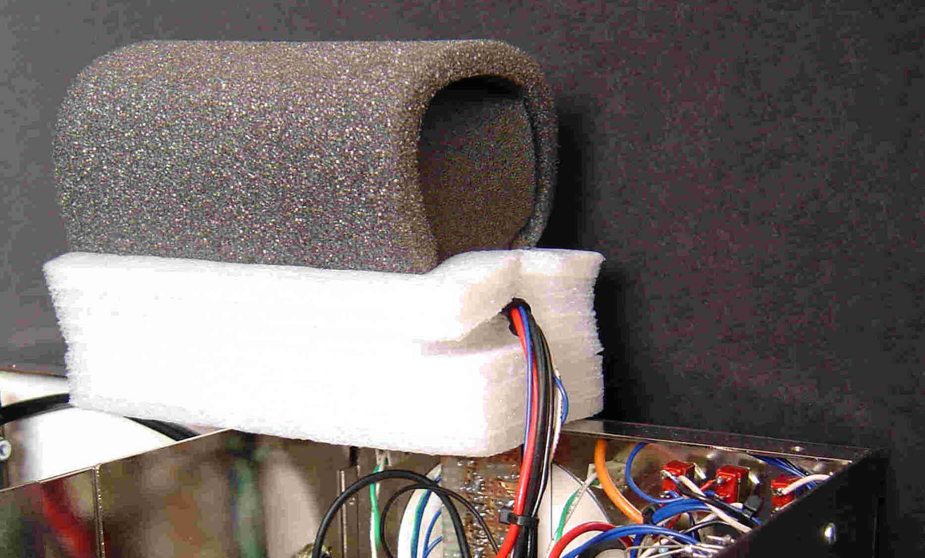
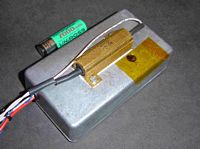
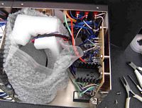
Below are a few images of the Mk-1 oven showing the mounting of the
heating element (33 Ohm 50 Watt resistor) and the thermal insulation used to
retain the heat.
Click on the thumbnail images to see the full sized pictures.
Constructional notes.
Hopefully
the three images and text above give enough detail to enable others to
implement a similar oven design. Here are a few extra notes to help. My
advice to anyone not familiar with this type of circuit would be to
build the control circuit on a bread-board or a scrap of copper clad
board in order to get a "feel" for the operation of the circuit before
building the final version. I found this was very helpful when I built
my first version of the oven and the experience gained made setting up
of the "neat" version much more straight forward.
The first image above shows how the heating element (50 Watt resistor)
is mounted. The resistor is bolted to the metal oscillator enclosure
with a small amount of heat sink compound between the resistor and
enclosure surfaces to improve thermal contact.
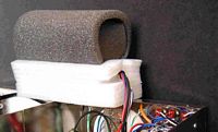
The second and third images above show one possible method of
providing suitable heat insulation to the oscillator enclosure. The
heat insulation I used was the foam padding previously used to package a
computer hard disk drive, this was simply "recycled" into its new role
as thermal insulation. The whole assembly was then placed in a "bubble
wrap" polythene bag to give a second layer of insulation.
One factor I found to be very important was the positioning of the
thermistor. In testing it was found that the oven performed at its best
when the thermistor was in contact with the enclosure and located as
close as possible to the heating element. I found the best way to
achieve this was to mount the heating element on the outside of the
enclosure and the thermistor on the inside of the enclosure directly
underneath the location of the resistor. The diagram below should make
this clear.
The
thermistor is held firmly in position by epoxy resin glue (Araldite),
also mounted close to the thermistor is a 10uF tantalum capacitor which
is used to decouple the thermistor and prevent any possible "pick-up"
by the thermistor connecting leads. The inclusion of this capacitor
means that the thermistor has to be connected to the rest of the
circuit taking care to observe the correct polarity for the capacitor.
For this reason I would suggest marking the wires or using colour coded
wires. e.g. Red for the positive terminal and black for the negative
terminal.
Tip.
The negative connection to the thermistor should not be connected to
the metal box or the oscillator circuit board to provide an earth return since this can lead to "earth loop"
problems and instability. Its better to bring the wires back to the temperature control board and connect them there.
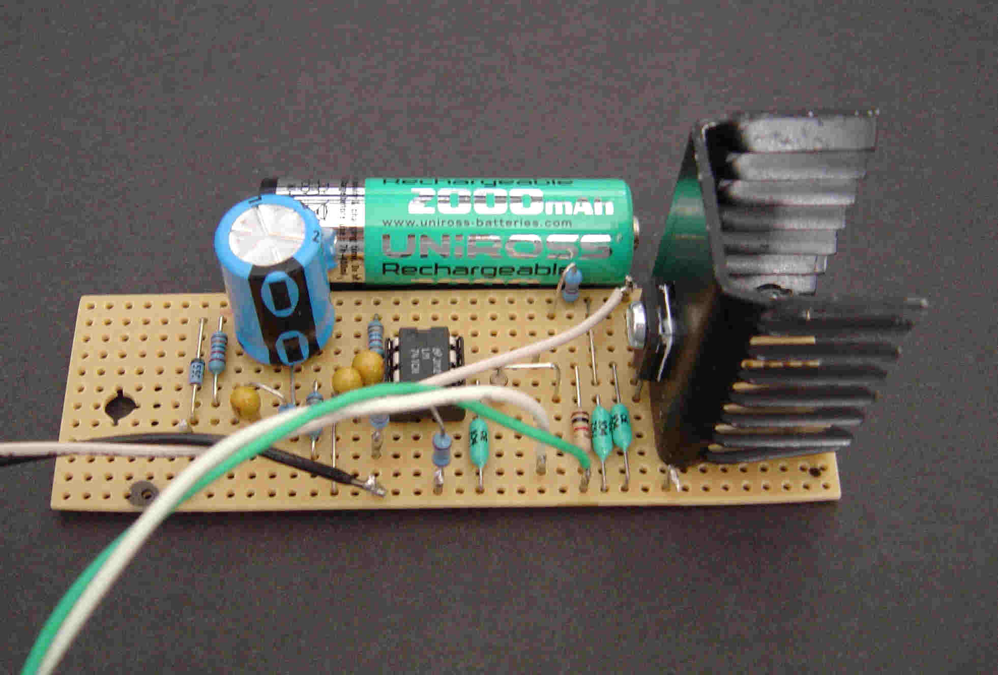
Below is an image showing the oven control board which was assembled
on a piece of strip board. Since the circuit is very stable
the layout is not too critical and the image is shown simply as a
guide. Note the small heat sink fitted to the BD681 Darlington.
Click on the thumbnail to see the full sized image.
Setting-up of the Mk-1.
The following set-up procedure assumes you have read the Important Note above.
Note, what follows is not the only possible method of setting up the
oven circuit but I have found it to be pretty reliable and
repeatable. You will need some form of temperature measuring device in
thermal contact with the oscillator enclosure in order to monitor the
temperature.
Temporarily replace the "S.O.T." (Select On Test) resistor (refer to Mk-1 schematic above)
with a 1 K-Ohm variable resistor, set this variable resistor to the
middle of its range. With the oven enclosure temperature at around 18
to 21 degrees centigrade (not critical) perform the following
procedure. Using a multimeter connect one probe to the junction of Ra
and Rb, (refer to Mk-1 schematic above) , now connect the other probe
of the multimeter to the junction of Rc and Rd. The reading should be
as close to zero Volts as possible. The polarity of the meter does not matter for this test as we only want to check for a zero Voltage condition.
If the reading is not at zero Volts then adjust the 1 K-Ohm
variable resistor until a zero Voltage reading is obtained. Now
observe the "oven-on" L.E.D. which may or may not be lit at this time.
If the L.E.D. is not lit then read on from the "If the L.E.D. is not lit" paragraph below. If the L.E.D. is lit then read on from the "If the L.E.D. is lit" paragraph below.
If the L.E.D. is not lit....
If the L.E.D. is not lit then adjust
the 1 K-Ohm variable resistor very carefully so as to reduce its value
and observe the L.E.D. As the value of the 1 K-Ohm resistor is reduced
(carefully) a point should be reached at which the L.E.D. lights up.
When this happens stop adjustment of the 1 K-Ohm variable resistor and
check the oscillator enclosure is warming up, this may take a few
minutes.
If the L.E.D. is lit....
If the "oven on" L.E.D. is lit up then carefully adjust the 1
K-Ohm variable resistor so its resistance is increased and observe the
"oven on" L.E.D. Continue to adjust the variable resistor until
the L.E.D. goes out then carefully adjust the variable resistor in the
opposite direction until the L.E.D. just lights up again and then stop
the adjustment.
Wait for a few minutes and check if the oscillator enclosure is warming
up, you should find that after a few minutes the L.E.D. goes out.
Now carefully adjust the 1 K-Ohm variable resistor to a slightly lower
value and the L.E.D. should light up again.
Keep observing the L.E.D. and if at any time the L.E.D. suddenly goes
out and the oven has not reached the desired temperature then re-adjust
the 1 K-Ohm variable resistor to a slightly lower resistance until the
L.E.D. again lights and then wait for the oven the warm up to the
higher temperature. Repeat this process until the oven reaches the
desired temperature. Then leave the oven on for a while without
altering the setting of the 1 K-Ohm variable resistor. Depending on how
well you have thermally insulated the oven you should now find the
L.E.D. goes on and off at regular intervals of around 30 seconds to 1
minute. These figures are only a guide and depend on the size of
enclosure, quality of thermal insulation and other factors.
The
adjustment of the 1 K-Ohm variable resistor must be done carefully
since the working threshold of the circuit is fairly narrow so slight
changes in resistance will make larger changes in the operating point
of the oven circuit. Remember, this is a bridge circuit and as such it
is quite sensitive to small changes.
When you are happy that the oven is operating correctly and at the
required temperature then switch off and carefully remove the variable
resistor taking care not to alter its setting. Now measure the value of
the variable resistor and fit a resistor or combination of
resistors which correspond to the same value as the variable resistor
setting and place them in the position of the S.O.T. component. Switch
on again and re-check the operation and working temperature of the
oven. If you have measured the variable resistor value carefully and
replaced it with a closely matched fixed resistor then the
temperature/operation should be correct. Don t worry to much if the
exact temperature is a degree or two away from the target value, what
is important is that the final value of temperature remains constant.
So 38C is close enough to the 40C target so long as it stays at 38C
over time. I would not recommend leaving a
variable resistor in the circuit as a permanent fixture, in my
experience they are often prone to "drift" or failure.
Mk-2 Crystal Oven.
The Mk-2 oven is very similar in
design to the Mk-1 except for two important differences. Firstly, the
MK-2 was intended to be used in a small direct conversion receiver to
ensure stability of the crystal oscillator. Because of the small
physical size of the receiver and the desire to consume less energy it
was decided that only the crystal and its "trimming" inductor would
be temperature stabilized. Also the temperature of the Mk-2 has been
set to 30C which is around 10 degrees lower than the Mk-1. Since my
shack has never reached anywhere near 30C I felt this was justified and
also saves energy.
Secondly I wanted to find an alternative to the NTC thermistor used in
the Mk-1 since this could be the one component which may prove
difficult to obtain in the future. Therefore the thermistor has been replaced by a
small signal transistor which acts as the temperature sensor in the
Mk-2.
How and why the transistor heat sensor works.
In any transistor the forward biased base/emitter junction current will
increase with temperature. This increase of current with temperature in
the base/emitter junction also causes a corresponding and amplified
increase in emitter/collector current through the device. With an NPN
transistor this change of current with increasing temperature results
in a fall in collector Voltage. Conversely, when the device temperature
falls the collector Voltage will rise. This change of Voltage can be
used as an indication of the junction temperature of the transistor and
of the temperature of anything it happens to be in thermal contact
with.
The schematic for the MK-2 appears below, click on the image to see the full sized drawing.
The
operation of the Mk-2 is essentially the same as the Mk-1 except that
the thermistor has now been replaced with an easily obtained NPN small
signal transistor. The operation of the circuit remains the same and
the explanation for the operation of the Mk-1 equally well explains the
operation of the Mk-2 with one exception. In the Mk-1 the oven
operation behaves more like a switch with a definite on-off operation.
Because of the thermal inertia of the enclosure this is acceptable. In
the Mk-2 however it was felt that the much lower thermal inertia
of the crystal encapsulation might lead to small changes in frequency
each time the oven switched on and off. To ensure this does not happen
a 2M2 (two-point-two Mega Ohm) resistor was fitted between the output
of the op-amp and the inverting input. This negative feedback has the
effect of
changing the operation of the oven such that after the initial
warm-up period the oven does not switch off but simply reduces the
supply of current to the heating elements/resistors. As the temperature
falls the current to the heating elements/resistors is increased again
but the whole process is more gradual and results in a "mean"
current being established in the heating elements/resistors such
that just enough energy is dissipated so as to maintain the desired
temperature. This action can be seen by observing the indicator L.E.D.
connected in parallel with the heating elements/resistors. When first
switched on the L.E.D. will be at full brilliance but after a few
minutes the oven reaches its operating temperature and the L.E.D.
"dims" slightly indicating the current through the heating
elements/resistors has also reduced. Thereafter the L.E.D. will remain
on with only slight alteration in brightness as the circuit performs
its function. In tests the value of the feedback resistor
proved to be non-critical and values from 1 Mega Ohm to 5 Mega
Ohms all worked. 2.2 Mega Ohms just happened to be convenient and gave good results.
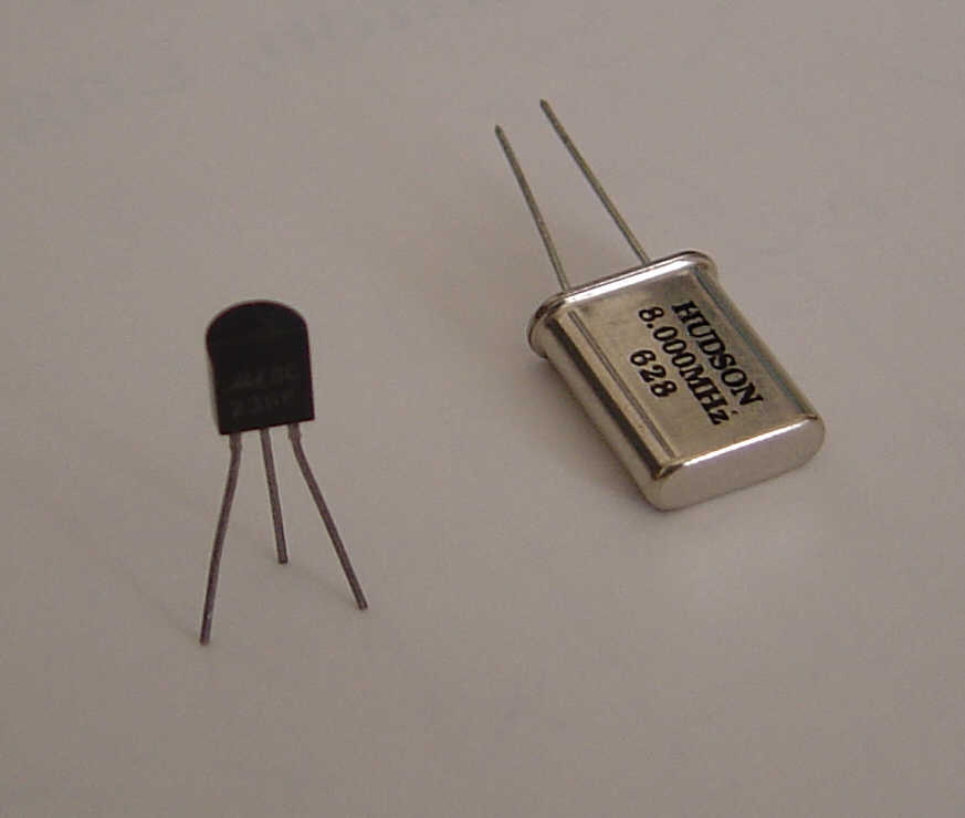
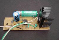
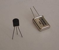
Construction.
Compared with the Mk-1 some
minor differences exist
in the construction of the Mk-2 circuit. These minor differences
include
the heating element for the crystal which now comprises of just two 100
Ohm resistors in series mounted on the crystal body with epoxy resin
glue. The temperature sensor transistor is also mounted on the crystal
body on the same side as the heating elements/resistors. Finally, any
inductors that may be required to "trim" the crystal frequency can
also be secured to the crystal body on the opposite side to the heating
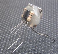
element/resistors. This is shown in stages in the images below. Also
shown in the images below is the Mk-2 control board which is built
on a small piece of strip board. Note that because of the reduced power
dissipation and lower currents involved with the heating
elements/resistors the BD681 Darlington no longer requires a heat sink
to be fitted.
Click on the thumbnails to see the full sized images.
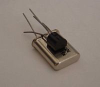
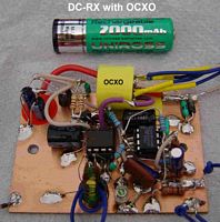
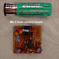
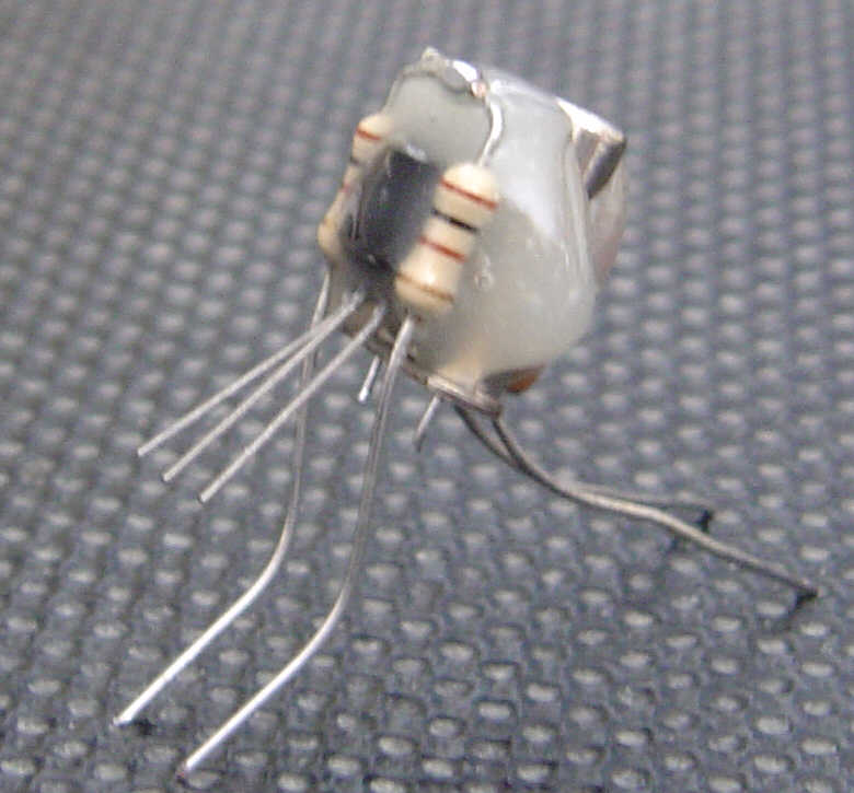
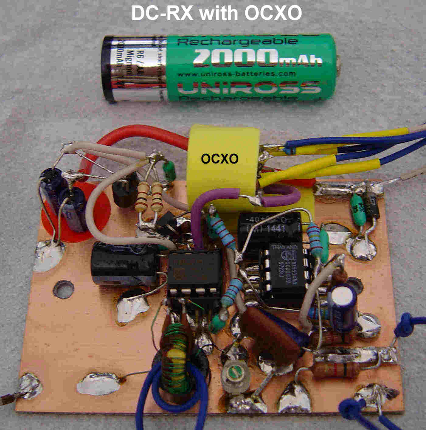
The fourth image above shows the
crystal mounted in my 30 Mtr DC-RX with some yellow thermal insulation
wrapped around it and the final image shows the Mk-2 oven
control board which is built on a small piece of strip board.
Setting-up.
The
first thing to do is select a suitable device for Q1 (see schematic
above) which can be almost any NPN small signal transistor. I used a
BC238B plastic packaged device because it had one flat face ideally
suited for attachment to the crystal body (see photographs above)
and I already had several of these in my junk-box. With a 10 K-Ohm resistor in
the collector and a 2M2 (two-point-two Mega Ohm) resistor
from the collector to the base (as shown in the schematic above)
connect your supply between the free end of the 10 K-Ohm resistor
(Positive connection) and the emitter (Negative connection) of Q1. The
supply should be set to12 Volts or whatever Voltage you intend to
operate your oven circuit from. If you do not intend using a stabilized
supply and plan to fit the 10 Volt zenor (shown in the schematic
above) then for this test set your supply to 10 Volts. Now measure the
Voltage on the collector of Q1 with respect to the negative supply
rail. The Voltage on the collector should be very nearly half the
supply Voltage (5 Volts in the schematic above) at 21 degrees-C but
don't worry if its not. Simply replace the 2M2 (two-point-two Mega Ohm) resistor
for another one until you get the required half supply Voltage at
around 21 degrees-C. Increasing the value of this resistor will reduce
the forward bias on Q1 and cause the collector Voltage to rise,
reducing the resistor value will increase the forward bias on Q1 and
cause the collector Voltage to fall. If selection of a suitable value
of resistance proves difficult then try a different transistor for Q1
and repeat the operation.
When you are happy that you have
selected a suitable device for Q1 and found a suitable biasing resistor
you can then attach the transistor to the crystal body (see images
above as a guide) along with the two series connected 100 Ohm heating
elements/resistors. When the glue has set solder the 10 K-Ohm collector
resistor, the base biasing resistor and the 100 nF capacitor to Q1
"ugly style" but as neatly as possible and use more glue if required to
secure the components. Finally, bring three identifiable wires out from
the Q1 circuit which will connect to the oven control board. The three
wires are connected to Q1's emitter, Q1's collector and the free end of
the
10 K-Ohm collector resistor.
Tip.
The negative connection to the transistor emitter should not be connected to
the metal box or oscillator circuit board to provide an earth return since this can lead to "earth loop"
problems and instability. Its better to bring the wires back to the temperature control board and connect them there.
The
final stage of setting-up is to select a suitable resistor for the
S.O.T. (Select On Test) resistor (see schematic for Mk-2 oven above)
which should be about 9K1 as a starting point. Using some sort of
temperature measuring device check the temperature of the crystal body
and switch on the oven circuit, the "power-on" and "oven-on" L.E.D.'s
should light up. After a short time the crystals temperature should start to
rise.
At around 30 degrees-C the temperature should stabilize, if the
oven does not reach 30C then reduce the value of "S.O.T" by about 50
to Ohms and re-check the stabilized temperature. If the
temperature is
now to high then increase the value of "S.O.T." slightly. Continue
adjusting the value of "S.O.T." until the desired temperature is
achieved. Selection of S.O.T. can be done more quickly by using one fixed
and one variable
resistor in place of the S.O.T. component. A fixed resistor of
around 8 K-Ohms with a 2 K-Ohm variable resistor in series should prove
satisfactory. When the correct setting has been found these components
can then be
carefully removed, the total resistance of the two series
components measured and then replaced by a fixed
resistor or resistors of the correct value. I would not recommend
leaving a variable resistor in the circuit as a permanent fixture, in
my experience they are often prone to "drift" or failure.
The Mk-3 Crystal Oven.
O.K.... So there is no Mk-3 oven...
yet! But if/when it arrives (still at the "back of my mind stage") it
will most likely retain many of the "tried and tested" features of the
Mk-1 and Mk-2. The junk box signal transistor temperature sensor and
the "tame" 741 op-amp will be retained. To reduce power consumption and
improve efficiency the BD681 could be used as the crystal heating
element by attaching it to the crystal and using the power dissipation
in the device to heat the crystal. This would improve efficiency
because it would be the only component dissipating any significant
energy. The Mk-2 is pretty good but wastes some energy as heat in the
BD681 which is simply lost. By dispensing with the heater
element/resistors and using the BD681 itself to heat the crystal the
efficiency should be slightly higher.
If this sounds like such a good idea you simply can't wait for the Mk-3
then have a look at the QRSS page of G4OEP (just over half way down) in
which he has presented a design which operates in a manner very
similar to the description above. The only significant difference is
that the design uses a thermistor as opposed to the junk box transistor
used in the Mk-2 oven above. With a little ingenuity the features of
both circuits could be combined.
The QRSS page of G4OEP
I hope this has proved interesting and useful.