G8JNJ 432 MHz Mixed Mode Helical Antenna
                      radiation pattern at 2 meters above groundG8JNJ 432 MHz Mixed Mode Helical Antenna NEC Model

Illustration of NEC-2 GH Helix Card

by Dr. Carol F. Milazzo, KP4MD (posted on 04 Nov 2015)
E-mail: [email protected]

CONTENTS
  • Introduction
  • 4nec2 Model
  • References
  • Return to KP4MD home page
  • INTRODUCTION

    To illustrate the application of the NEC-2 GH helix command in the 4nec2 antenna modeling program1, here is an annotated 4nec2 model of an interesting omnidirectional circular polarization 70 cm helical antenna by Ehrenfried2 that demonstrates the use of the NEC-2 GH command3 to automate the helix segment construction and the GM command4 to elevate the helix above ground. This method is superior to manually calculating the coordinates of each segment.  I also demonstrate the use of the GH command to construct loops as zero pitch helices in my Universal Magnetic Loop Antenna models5 and 144 MHz Halo model analysis6.


    SWR and Reflection Coefficient
    SWR and Reflection Coefficient vs. Frequency
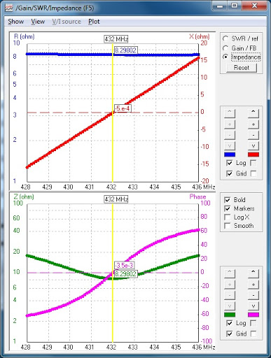
    Impedance vs. Frequency
    Impedance vs. Frequency
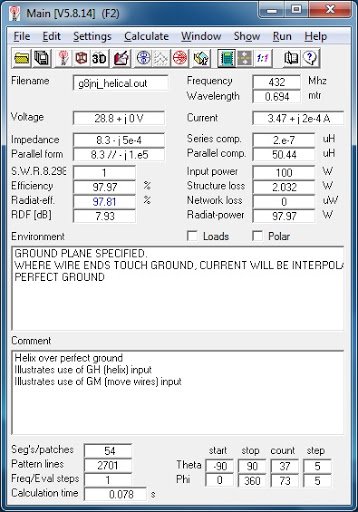
    4nec2 Model Calculation
    Model Calculation
    Gain vs. Frequency
    Gain vs. Frequency

    G8JNJ 432 MHz Mixed Mode Antenna Model

    G8JNJ's interesting Mixed Mode Helix antenna
                    (versions for 70 cm and 2 m) provides
                    omnidirectional gain and circular polarization -
                    good for both terrestrial and satellite operation.
                    Simple construction.
                    http://www.g8jnj.net/mixedmodehelical.htm

    CM Helix over perfect ground
    CM Illustrates use of GH (helix) input
    CM Illustrates use of GM (move wires) input
    CE
    SY f=432 'Input Frequency MHz
    SY k=308.756 'Input Velocity constant ~300 Mm/s
    SY w=k/f 'Calculate Wavelength in space
    SY hw=0.5*w 'Calculate Half wavelength in space
    SY t=3 'Input Number of helix turns
    SY ts=18 'Input Segments per helix turn
    SY n=t*ts 'Calculate Segments total
    SY wl=0.5 'Input Antenna height in wavelengths
    SY l=wl*w 'Calculate Antenna height in meters
    SY s=l/t 'Calculate Turn spacing in meters
    SY r=sqr(hw*hw-s*s)/2/PI 'Calculate Helix radius in meters
    SY d=.0025 'Input Wire radius in meters
    SY h=2 'Input Height above ground in meters
    GH 1 n s l r r r r d
    GM 0 0 0 0 0 0 0 h 0
    GE 1
    LD 5 0 0 0 58000000 'copper
    GN 1
    EK
    EX 0 1 n/2 0 1. 0 0
    FR 0 0 0 0 f 0
    EN

    REFERENCES

    1. 4nec2 Antenna Modeling Program, Voors, A
    2. "70 cm Mixed Mode Helical Antenna", Ehrenfried, M, G8JNJ
    3. Helix Spiral Specification (GH), NEC-2 Reference
    4. Coordinate Transformation (GM), NEC-2 Reference
    5. "A Universal HF Magnetic Loop Antenna NEC Model", Milazzo, C, KP4MD
    6. "144 MHz Halo Antenna", Milazzo, C, KP4MD
    7. Download 4nec2 Model File, Milazzo, C, KP4MD
    Return to KP4MD Home Page
    Top