BUTTERWORTH FILTER DESIGN

Milazzo, Carol F., KP4MD, "Butterworth Filter Design", QZX, Vol 2:4, March 1984, pp. 3-5. A Sinclair BASIC program to design Butterworth low-pass, high-pass, band-pass and band-stop filters.

Theory

This program for the Timex-Sinclair 1000 computer was written for completely automated design of Butterworth low-pass, high-pass, band-pass or band-stop filters. Modern solid-state transmitters are more prone to harmonic and parasitic frequency radiation, and therefore it is desirable for the radio amateur to have access to modern filter design in order to comply with present FCC rules for purity of emissions. Butterworth filters are superior to image-parameter filters (constant-k and m-derived) in their efficiency and response characteristics. For further details on the theory of modern filter design, the reader is referred to recent editions of the Radio Amateur's Handbook and to the text Electronic Filter Design Handbook (Mc-Graw-Hill, 1981) by Arthur B. Williams, from which the formulas used in this program were derived.

Operation

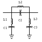
The Butterworth filter is composed of a series of "branches" which are alternately connected in series or shunt with the source-to-load path. In low-pass and high-pass filters, each branch is either a capacitor or an inductor. In band-pass and band-stop filters, each branch is either a series or parallel resonant circuit composed of a capacitor and an inductor. (see figures 1 and 2). The first branch of any filter may be selected as either a series or a shunt branch.

Upon running the program, the user must first specify if a low-pass/high-pass or a band-pass/band-stop filter is desired. If the low-pass high-pass design is chosen, the user must then specify two frequencies in Hz, each followed by the respective attenuation desired (this may be a very small value but never exactly zero). The source resistance must then be specified. The program will then calculate and display the minimum number of branches required for the specifications, and request if the first branch is to be series or shunt. The program will then calculate all required component values rounded to 3 significant digits and displayed in the most common units. The rounding feature may be eliminated by changing statement 830 to "LET X1=X". The program will then provide a table of attenuation vs. frequency for any specified range and increment of frequency.

If the band-pass/band-stop design is selected, the process is similar except that first the center frequency of the filter must be specified, and then two frequency bandwidths with their respective attenuations. These filters are geometrically symmetrical, i.e. the center frequency is not exactly the arithmetic average of the limit frequencies of any bandwidth. The relationship is really fc=SQRT(f1xf2).

The given examples demonstrate the use of this program. The first filter designed is a band-stop filter for 11 meters, providing 20 dB attenuation over 26.965 to 27.405 MHz (bandwidth of 440 kHz) and only 1 dB attenuation over 26.37 to 28.0 MHz (bandwidth of 1.63 MHz). This type of filter may be designed for the input of a linear amplifier to prevent operation on the 11 meter band while permitting operation on the 10 meter band. This filter requires only 3 branches (total of 6 components), and its response over 26 to 28 MHz is shown in the printout.

The second example shows design of a low-pass filter, such as used for TVI suppression.. An attenuation of 30 dB is specified at 54 MHz, while a loss of 1 dB is specified at 28 MHz. This filter would require 7 elements, and its response over 5 to 55 MHz is shown in the table.

This program offers the radio amateur the ability to synthesize modern Butterworth filter circuits with all calculations performed by a computer. All previously published articles in amateur magazines on this subject present tables of normalized filter values or only a few "typical" values for certain common frequencies. This program offers the full flexibility possible by using the original formulas for synthesis of Butterworth filters. It is possible to write such programs for Chebyshev and other modern filters, and these will require slightly more complicated formula derivations. This is one of the author's future projects for programing on the Timex Sinclair 1000.

BANDSTOP FILTER DESIGN

CENTER FREQUENCY 27.185 MHZBANDWIDTH
FREQUENCY       ATTENUATION (DB)    
440000          20
1630000         1
RESISTANCE (OHMS): 50
NO BRANCHES=3
1ST EL. (SERIES=1, SHUNT=-1) -1

BANDSTOP FILTER COMPONENTS

BRANCH 1 SHUNT
L 1 = 6.12 UH IN SERIES WITH
C 1 = 5.6 PF

BRANCH 2 SERIES
C 2 = .00122 UF IN PARALLEL WITH
L 2 = .028 UH
BRANCH 3 SHUNT
L 3 = 6.12 UH IN SERIES WITH
C 3 = 5.6 PF

Figure 1. 27 MHz bandstop filter.

FREQUENCY RESPONSE CURVE

FREQUENCY RANGE (HZ)
LOWER LIMIT: 26000000
UPPER LIMIT: 28000000
IN STEPS OF 100000

FREQUENCY HZ    ATTENUATION DB
26000000        0.10273635
26100000        0.17496129
26200000        0.31124634
26300000        0.580021
26400000        1.1286903
26500000        2.2531149
26600000        4.4293654
26700000        8.1439241
26800000        13.677399
26900000        21.404383
27000000        32.684123
27100000        52.995257
27200000        98.242908
27300000        45.214405
27400000        28.962848
27500000        19.105926
27600000        12.18576
27700000        7.2439357
27800000        3.9779707
27900000        2.0779733
28000000        1.0813628

LOWPASS FILTER DESIGN

FREQ MHZ        ATTENUATION (DB)
28              1
54              30
RESISTANCE = 50 OHMS

NO. BRANCHES=7
1ST EL. (SERIES=1, SHUNT=-1) -1

LOWPASS FILTER COMPONENTS

BRANCH 1 SHUNT
C 1 = 45.9 PF

BRANCH 2 SERIES
L 2 = 0.322 UH

BRANCH 3 SHUNT
C 3 = 186 PF

BRANCH 4 SERIES
L 4 = 0.516 UH

BRANCH 5 SHUNT
C 5 = 186 PF

BRANCH 6 SERIES
L 6 = 0.322 UH

BRANCH 7 SHUNT
C 7 = 45.9 PF

Figure 2. Low-pass filter.

FREQUENCY RESPONSE CURVE

FREQUENCY RANGE         HZ
LOWER LIMIT:            5000000
UPPER LIMIT:            55000000
IN STEPS OF             5000000

FREQUENCY HZ    ATTENUATION DB
5000000         0
10000000        6.1681405E-7
15000000        .00018030821
20000000        .010107901
25000000        0.22420646
30000000        2.2537036
35000000        8.3804788
40000000        15.930315
45000000        23.001189
50000000        29.390423
55000000        35.181716

Program Listing

10 DIM A(2)
20 DIM F(2)
30 PRINT "BUTTERWORTH FILTER DESIGN","SELECT LOW PASS/HIGH PASS (0)"," OR BANDPASS/BANDSTOP (1)"
40 INPUT Q
50 CLS
55 IF NOT Q THEN GOTO 90
60 PRINT "CENTER FREQUENCY: ",
70 INPUT F0
80 PRINT F0,,,"" BANDWIDTH
90 PRINT AT 3,0," FREQUENCY ATTENUATION(DB)"
100 FOR K=1 TO 2
110 PRINT K;". ";
120 INPUT F(K)
130 PRINT F(K),
140 INPUT A(K)
150 PRINT A(K)
160 NEXT K
170 PRINT "RESISTANCE = ",
180 INPUT R
190 PRINT R;" OHMS",,,
200 LET N=LN ((10**(.1)A(1))-1)/(10**(.1*A(2))-1)/(2*LN (F(1)/F(2)))
210 LET S=SGN N
220 LET N=INT (ABS N+.9)
230 PRINT "NO. BRANCHES=";N
260 LET FC=F(1+(A(1)>A(2)))*(10**(.1*A(1+A(1)>A(2))))-1)**(-.5/S/N)
270 PRINT "1ST EL. (SERIES=1, SHUNT=-1) ";
280 INPUT T
290 PRINT T
300 CLS
310 LET A$="LOW "
320 LET B$="PASS"
330 IF S<0 THEN LET A$="HIGH "
340 IF Q THEN LET A$="BAND"
350 IF Q AND S<0 THEN LET B$="STOP"
360 PRINT A$;B$;" FILTER COMPONENTS",,,
370 FOR K=1 TO N
380 PRINT "BRANCH ";K;
390 IF T>0 THEN PRINT " SERIES"
400 IF T<0 THEN PRINT " SHUNT"
410 LET X=(2*SIN ((2*K-1)*PI/2/N))**S/2/PI/FC*R**(S*T)
420 GOSUB 800
430 LET T=-T
440 IF NOT Q THEN GOTO 500
450 PRINT " IN ";
460 IF S*T>0 THEN PRINT "PARAL. W/"
470 IF S*T<0 THEN PRINT "SERIES W/"
480 LET X=1/(4*PI*PI*F0*F0*X)
490 GOSUB 800
510 PRINT
520 NEXT K
530 COPY
540 PRINT
550 PRINT "ATTEN. VS. FREQ."
560 PRINT "FROM?";
570 INPUT I
580 PRINT I,"TO?";
590 INPUT J
600 PRINT J,"IN STEPS OF?"
610 INPUT K
620 PRINT K
630 CLS
640 PRINT "FREQUENCY HZ","ATTENUATION DB"
650 FOR H=I TO J STEP K
660 LET H1=H
670 IF Q THEN LET H1=ABS (H-F0*F0/H)
680 PRINT H,10*LN (1+(H1/FC)**(2*S*N))/LN 10
690 NEXT H
700 COPY
710 INPUT Q$
720 CLS
730 GOTO 10
800 IF S*T>0 THEN PRINT " L";STR$ K;" = ";
810 IF S*T<0 THEN PRINT " C";STR$ K;" = ";
820 LET E=INT (LN X/LN 10)
830 LET X1=10**(E-2)*INT (X*10*(2-E)+.5)
840 IF E<0 THEN GOTO 870
850 PRINT X1;" ";
860 GOTO 940
870 IF E<-3 OR S*T<1 THEN GOTO 900
880 PRINT 1E3*X1;" M";
890 GOTO 940
900 IF E<-9 AND S*T<1 THEN GOTO 930
910 PRINT 1E6*X1;" U";
920 GOTO 940
930 PRINT 1E12*X1;" P";
940 IF S*T>0 THEN PRINT "H";
950 IF S*T<0 THEN PRINT "F";
960 RETURN
9900 SAVE "FILTER"
9950 RUN