|
THE
MITCH LEE RECEIVER
NOTE: This page is here for historical purposes, as well as for the benefit of anyone who may wish to build the set, or derive ideas from it's circuitry. I no longer have it as I have since bought a commercial rig that DOES greatly exceed the capabilities of this set as presented, though at a MUCH more expensive price of approximately 2,600 US Dollars. It is a Yaesu FT-2000 transceiver. So the statement "For DXing NDB's this receiver easily outperforms any of the commercial receivers I've had." is no longer valid. However, it DOES still have a very good performance/cost ratio. First, I want to say that this receiver is unconventional. It is a "one trick pony" suitable only for CW or QRSS modes. The IF amplifier is an unusual design in which the selectivity is obtained by use of 5 common base transistor stages, each with it's own individual Crystal. It has very sharp, near DSP selectivity. Ultimate selectivity isn't great, but for this application that doesn't seem to detract from it's performance. For steeper skirts the receiver could be used with an audio DSP unit, but I don't feel this is necessary. For DXing
NDB's this receiver easily outperforms any of the commercial receivers
I've had. It is also very quiet (Noise is in inverse
proportion to
bandwidth). There is some filter ringing in the narrow IF
strip.
This selectivity is accomplished without breaking the bank as it uses readily obtainable parts. Crystals don't need matching as each stage is individually tuned. NOTES: 1. HOWEVER, there is one caveat! This is a fairly elaborate project for the homebrewer and should not be undertaken as a first time homebrew project. If good construction practices and shielding aren't used I will almost guarantee it will be unstable and oscillate. My unit is built on a double sided subchassis constructed of double sided copper clad PC board. There are separate compartments for each of the IF stages, Mixer stage, Preselector, Product detector and Audio section. 2. The plans are not a kit with step by step instructions, but rather are provided as a rough guide only. If, after looking at the schematics and data in the PDF file, you say "Huh?", this is NOT the set for you to build! The builder should be prepared to go shopping and looking for parts and have a pretty good general idea of what features they want it to have. The basic circuit has no bells and whistles such as AGC, memories, etc but the builder may add their own extras. It is unlikely any two ML receivers will look the same, have identical circuits or even perform alike. 3. Because of this selectivity one must use a stable VFO of 2.0 to 2.50 MHz having very small tuning steps, preferably 1 Hz steps. I used the DDS daughtercard available from NJQRP at http://www.njqrp.org/dds/ . I'm using a PIC controller and it's working very well. I understand that FAR circuits now offers a kit with the DDS and PIC controller on a single board. 4. The design is merely a platform for you to build the beacon receiver of your dreams around, and it opens up a whole world of circuit exploration. My particular unit uses an MCL TFM2 mixer, has the ability to select between two IF strips of different bandwidth, built in preselector tuning 9KHz through 530 KHz, an audio notch filter with a 1 Hz wide notch and a simple audio AGC circuit in the NE602 product detector. 5. Construction note: Good quality DBMs (Double Balanced Mixers) that perform well down to 10 KHz are difficult to find and expensive. What is less well known is that most good quality DBMs will operate down to nearly DC by swapping the RF and IF ports, resulting in only slight reduction in performance. This is what I did with the TFM-2 mixer. Here are the actual measured selectivity specifications on my particular receiver. The filter results are referenced to -10dBm audio level at the line output jack. Audio samples are of a relatively strong beacon
SELECTIVITY
********************************
Listen to
Narrow BW
* Narrow IF strip: * * -3dB 11 Hz wide (-6 & +5) * * -6dB 16 Hz wide (-8 & +8) * * -9dB 21 Hz wide (-10 & +11) * * -12dB 27 Hz wide (-13 & +14) * * -18dB 38 Hz wide (-18 & +20) * * -24dB 56 Hz wide (-29 & +27) * *********************************
******************************** Listen to Wide BW
* Wide IF strip: * * -3dB 35 Hz wide (-7 & +28) * * -6dB 45 Hz wide (-13 & +32) * * -9dB 53 Hz wide (-18 & +35) * * -12dB 64 Hz wide (-24 & +40) * * -18dB 89 Hz wide (-40 & +49) * * -24dB 118 Hz wide (-59 & +59) * **********************************
SOME
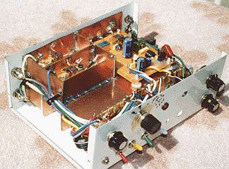
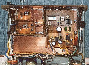
PICTURES OF MY UNIT
Front and top views of my version of the Mitch Lee Receiver. NOTE: At least 80 percent of the circuitry is in compartments UNDER the the subchassis and not visable here.
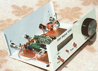
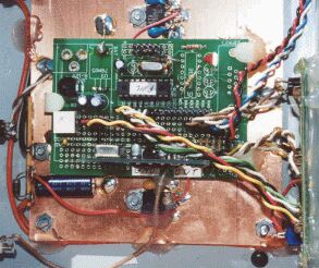
Front and top
views of the DDS VFO used with the Mitch Lee receiver.
Controller is a
PIC and the DDS board is the NJQRP daughtercard. Melt Some Solder!
 |