|
Tunable
LF Preamplifier
On
this page are plans for a versatile and high quality preamplifier
suitable for LF work right up through the lower broadcast
band.
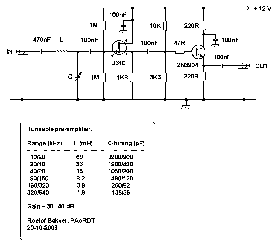
First, a little history behind this unit and some well deserved credits. For several years I built and used a number of "Universal Preamps". It was designed by Lyle Koehler and is available for download from the web. It works very well and Lyle is to be commended for a good design. See Lyle Koehler's Circuit However, I had a need for a preamplifier with a gain of 40 to 50dB for use with an LF modified R-390A receiver. I decided to see what I could do in "rolling my own". The result was a three stage amplifier using a FET follower having two Bipolar transistor stages following it. To improve it's dynamic range and insure that it was "Bullet proof" from IMD products, rather than direct coupling, each stage received full Vcc Voltage and relatively high high device currents,. Unfortunately, I used a high quality but obscure FET that I had on hand. This made it difficult to reproduce. Roelof in the Netherlands expressed an interest in building one. I sent him some rough hand drawn schematics of the circuit. Not needing 40-50dB of gain, he revised the circuit down to two stages with a gain of 30-40dB. Overall gain is somewhat dependent on the quality (Q) of the coils used. It is reminescent of the original "Universal Preamp", but each stage is independent rather than being direct coupled. Instead of the usual MPF-102, it uses the higher quality and more consistent J310 FET. View the J310 FET page COILS: IF you are able to obtain them, high quality Pot core coils are by far the best, but the circuit will work with toroids (2nd best) or even small RF chokes of the variety often pulled from scrapped electronic gear. I have used all three options in various amplifiers and all will work. The better coils provide sharper selectivity and higher gain. Besides their high "Q", the advantage of Pot Core coils and Toroids are their "self shielding" qualities. This will help minimize inductive pickup of strong carriers and other interference from adjacent Computer monitors, TV's etc. Additional inductors may be switched in/out to obtain other tuning ranges (use the LC Resonance formula to calculate desired Inductance). Roelof drew the schematic of the final unit and has kindly developed a chart showing the tuning range of various capacitors and inductors. The input tuned circuit is comprised of components L and C at the input of the preamp. A wide variety of tuning capacitors may be used. I usually favor a dual gang receiving type variable capacitor with maximum capacity of 365 to 450 pF per section. Using one gang with a 3.3uF inductor will cover the entire NDB band. I typically tie the two sections in parallel to give a greater maximum capacity. In addition to providing selectivity, the tuned circuit matches the low input impedance to the high input impedance of the FET. VARACTOR NOTE: Instead of using a discrete tuning capacitor you may substitute a "Quad" of Varactors if you wish. I personally feel the old variable capacitor works better, but if compactness is important then go with the Varactors. View Varactor Primer Page FINAL NOTE: I ALWAYS build these preamps with a 510KHz Low Pass filter having at least 5 Poles preceding the Inductor "L". This is to prevent broadcast band stations from producing heavy IMD interference in the LF range. View Low Pass Filter Page THE CIRCUIT:  Melt
Some Solder!

|
