Modeling the Firestik Antenna by Dick Reid, KK4OBI
The Firestik line of antennas have been around since 1975… so has
the Numerical Electromagnetics Code or NEC program for antenna
modeling. One would expect that antenna models for the Firestik type
of antenna would be available but nothing can be found on the
internet or by asking the Firestik Antenna Company.
Modeling a quarter-wave ground plane antenna like this has some difficulties
because the computer versions up to NEC 2 could not accommodate
elements touching ground. One related problem is the Automatic Gain
Test (AGT) which is used to validate a model. This requires a
ground. For the AGT test the “MiniNEC ground” is used to work
around this problem. It does this by creating a quarter-wave ground
plane near ground to balance the other half of the radiation. For this
article the MiniNEC
approach was used to simulate a Firestik. A model was constructed
with a ground plane of 24 radials set 1 inch over ground. On this
radial field was set a 3/8 inch vertical element varying between 2, 3
and 4 feet tall.
Top Loading
How best to load the vertical was a study. Only knowing that the
loading section was about 1 foot long, the question was: “How long
is the actual loading coil”. To explore this question models were
set up using different segment lengths, 4.0 inch and 4.8 inch. This
makes it possible for the 4NEC2 antenna modeling program to compare
loads of 8.0, 9.6 and 12 inches long positioned on the top of 2, 3
and 4 foot Firestik antennas.
The study was at
27.2 MHz, which is the center of the 40 channel
Citzens Band, (CB).
To resonate the
vertical element in the 4NEC2 program do this: Source/Load tab, Load(s),
Type, then select Series-RLC.
Set Symbol R in
the range of 10 to 13 Ohms resistance. Not critical.
Symbol C is
essentially stray capacitance in the winding of 5 or 6 pF (10-12
Farad).
The inductance
(Symbol L) is critical... around 16-17 uH (10-6 Henry)
for a 2 segment load; 11-12 uH for a 3 segment load.
The optimizer
function is used to find the best uH value.
See results of
the study in Table
1 following.
4NEC2 Comparison of Firestik Top Loading
Table 1
8
Inch Top Load
Gain
dBi
%
Effic.
Z
Ohms
SWR
50
2
Feet
-11
40.94
33.0
1.54
3
Feet
-7.8
49.58
36.8
1.38
4
Feet
-5.8
59.88
39.1
1.28
9.6
Inch Top Load
Gain
dBi
%
Effic.
Z
Ohms
SWR
50
2
Feet
-11
44.3
28.0
1.63
3
Feet
-7.8
50.45
34.7
1.45
4
Feet
-5.8
60.44
39.0
1.32
12
Inch Top Load
Gain
dBi
%
Effic.
Z
Ohms
SWR
50
2
Feet
-12
31.82
37.5
1.33
3
Feet
-8.8
40.17
42.5
1.22
4
Feet
-6.6
50.51
44.2
1.1
From the above
table it is apparent that a 12 inch load produces
the lowest % Efficiency.
The 9.6 and 8 inch loading coils have higher % Efficiency. The 8
inch load offers better SWR. Accordingly, the
attached 4NEC2 computer models of 4 Foot, 3 Foot and 2 Foot antennas
use 8 inch top loading as the best approximation of a Firestik
design.
Mechanical Tuning
As described by
KC7VWM, tuning a Firestik antenna is done by a screw that is used to
adjust the length of the antenna. To simulate this adjustment method
in the 4NEC2 antenna model a programmable symbol “Tune” is
incorporated. Using this “Tune” symbol provides the means to
predict how much a change in length causes how much change in
frequency.
Tuning adjustment study was in steps of 0.05, 0.1 and 0.15 feet above and
below the model length at 27.2 MHz. That is equal to steps of 0.6”,
1.2” and 1.8”. At each change in length a Frequency Sweep was
made to determine the new Frequency MHz and SWR
The Length change
vs. Frequency change results for 4 foot, 3 foot and 2 foot
Firestik-type antenna modelss are summarized in the graphs following.
Note that all the X and Y axis are identical so all curves are
directly comparable.
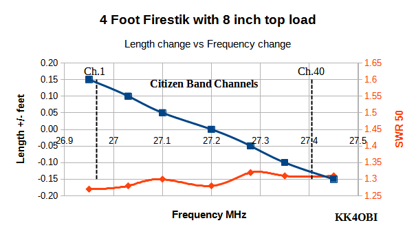
Graph 1
In graph 1 the tuning to Channel
1 is predicted to be longer by about 0.14 ft. (1.68”) and Channel 40
about -0.13 ft. (-1.56”) shorter.
The model indicates
low SWR with some non-linearity which may be an artifact in modeling.
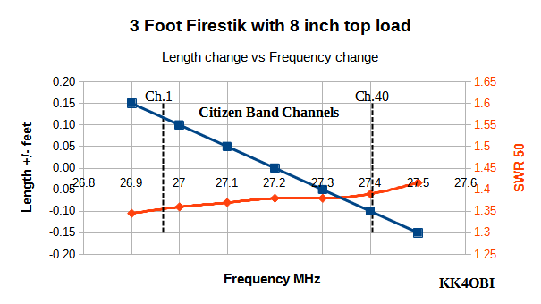
Graph 2
In Graph 2 the tuning for Channel 1 is predicted to be longer by about 0.12 ft. (1.44”) and
Channel 40 about -0.11 ft. (-1.32”) shorter.
SWR is higher than a 4 Foot Firestik with an almost linear rate of
change over the CB band.
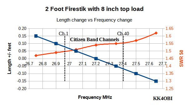
Graph 3
Graph 3 shows that tuning
is sensitive. Channel 1 tuning is predicted to be only about 0.06 ft.
(0.72”)
longer and Channel 40 only
about -0.07 ft. (-0.84”) shorter.
SWR is higher but still useful. Some slight non-linearity over the CB
band is noted.
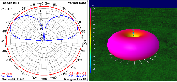
The
radiation pattern (below) is the same for all three antennas. Only the
Gain
and % Efficiency varies as seen in Table 1..
Firestik Polar Radiation Pattern
Figure 1
Appendix of 4NEC2
model for 4 ft. Firestik antenna
Copy the text between the double
horizontal lines and save as
Firestik 4ft.NEC.txt
To
use the NEC
model, remove “.txt” and run Firestik 4ft.NEC
=================
Start of 4 foot Firestik antenna model
===========================
CM
Since NEC2 can not allow anything touching ground, this model is set
to use the "Real" (Sommerfeld) ground so you can make the
radials close to ground.. The MiniNEC ground can be used but
generally not as good.
CM
CM
This is loaded by experinentally finding Inductance, capacitance and
resistance on the top two segments of the 4-foot x 3/8"diameter
vertical.radiator.
CM
4 FOOT FIRESTIK MODEL
CM
Radials are 8 feet of #14 coated wire (.00267radius) with 24 segs. 1
seg=8/20= 4 inches
CM
Vertical is 4 feet (48") of 3/8 dia (0.0156 radius) Segs =
48/4== 12. Use 12 segments
CM
Load the top 2 segments of 10 segments to simulate the Firestik top
loading.
CM
The model is tuned to mid-band at 27.2 MHz... around channel 20.
CM
A "Tune" section is adjusted to any CB channel.Longer =
Chan1-20. Shorter = Chan 20-40 (also 10m up to 28.5MHz)
CM
The advertised "5/8 wavelength" refers to the length of
wire used to wrap the stick... not frequency..
CM
CM
CE
SY
hgh=0.083 'In feet 1 inch =0.083 over ground
SY
Freq=27.2 'MHz
SY
H=1.741e-5 'Henries inductance
SY
F=5.24e-12 'Farads capacitance
SY
R=12.92 'Resistance
SY
Vert=4 'Height of vertical in feet
SY
Tune=0 'Tuning length added to vert
SY
Radius=0.00267 '00267=#14 wire radius
SY
Rad=8 'Length of radials feet
SY
Ang1=0 'Angles of each radial
SY
Ang2=15
SY
Ang3=30
SY
Ang4=45
SY
Ang5=60
SY
Ang6=75
SY
Ang7=90 '90 degrees
SY
Ang8=105
SY
Ang9=120
SY
Ang10=135
SY
Ang11=150
SY
Ang12=165
SY
Ang13=180 '180 degrees
SY
Ang14=195
SY
Ang15=210
SY
Ang16=225
SY Ang17=240
SY
Ang18=255
SY
Ang19=270 '270 degrees
SY
Ang20=285
SY
Ang21=300
SY
Ang22=315
SY
Ang23=330
SY
Ang24=345
GW 1 12 0 0 hgh 0 0
hgh+Vert+Tune 0.0156 'of
Vertical 3/8" radiator with load on top
GW 2 24 0 0 hgh Vert*Sin(ang1)
Vert*cos(ang1) hgh Radius 'of
#14 coated wire
GW 3 24 0 0 hgh Vert*Sin(ang2)
Vert*cos(ang2) hgh Radius ‘Radials
GW 4 24 0 0 hgh Vert*Sin(ang3)
Vert*cos(ang3) hgh Radius
GW 5 24 0 0 hgh Vert*Sin(ang4)
Vert*cos(ang4) hgh Radius
GW 6 24 0 0 hgh Vert*Sin(ang5)
Vert*cos(ang5) hgh Radius
GW 7 24 0 0 hgh Vert*Sin(ang6)
Vert*cos(ang6) hgh Radius
GW 8 24 0 0 hgh Vert*Sin(ang7)
Vert*cos(ang7) hgh Radius
GW 9 24 0 0 hgh Vert*Sin(ang8)
Vert*cos(ang8) hgh Radius
GW 10 24 0 0 hgh Vert*Sin(ang9)
Vert*cos(ang9) hgh Radius
GW 11 24 0 0 hgh
Vert*Sin(ang10) Vert*cos(ang10) hgh Radius
GW 12 24 0 0 hgh
Vert*Sin(ang11) Vert*cos(ang11) hgh Radius
GW 13 24 0 0 hgh
Vert*Sin(ang12) Vert*cos(ang12) hgh Radius
GW 14 24 0 0 hgh
Vert*Sin(ang13) Vert*cos(ang13) hgh Radius
GW 15 24 0 0 hgh
Vert*Sin(ang14) Vert*cos(ang14) hgh Radius
GW 16 24 0 0 hgh
Vert*Sin(ang15) Vert*cos(ang15) hgh Radius
GW 17 24 0 0 hgh
Vert*Sin(ang16) Vert*cos(ang16) hgh Radius
GW 18 24 0 0 hgh
Vert*Sin(ang17) Vert*cos(ang17) hgh Radius
GW 19 24 0 0 hgh
Vert*Sin(ang18) Vert*cos(ang18) hgh Radius
GW 20 24 0 0 hgh
Vert*Sin(ang19) Vert*cos(ang19) hgh Radius
GW 21 24 0 0 hgh
Vert*Sin(ang20) Vert*cos(ang20) hgh Radius
GW 22 24 0 0 hgh
Vert*Sin(ang21) Vert*cos(ang21) hgh Radius
GW 23 24 0 0 hgh
Vert*Sin(ang22) Vert*cos(ang22) hgh Radius
GW 24 24 0 0 hgh
Vert*Sin(ang23) Vert*cos(ang23) hgh Radius
GW 25 24 0 0 hgh
Vert*Sin(ang24) Vert*cos(ang24) hgh Radius
GS 0 0 0.3048
GE 1
LD 0 1 11 12 R H F
LD 5 1 1 12 58000000
LD 7 1 1 12 2.4
GN 2 0 0 0 4 0.003
EK
EX 0 1 1 0 1 0 0
FR 0 0 0 0 Freq 0
EN
============== End of 4 Foot
Firestik antenna model
====================================
Appendix of 4NEC2
model for 3 ft. Firestik antenna
Copy the text between the double horizontal lines and save as
Firestik 3ft.NEC.txt
To
use the NEC
model, remove “.txt” and run Firestik 3ft.NEC
====================== Start of 3
Foot Firestik antenna model
============================
CM
Since NEC2 can not allow anything touching ground, this model is set
to use the "Real" (Sommerfeld) ground so you can make the
radials as close to ground.. The MiniNEC ground can be used but
generally not as good.
CM
CM
This is loaded by experinentally finding Inductance, capacitance and
resistance on the top two segments of the 3-foot x 3/8"diameter
vertical.radiator.
CM
FIRESTIK 3 FT MODEL
CM
Radials are 8 feet of #14 coated wire with 24 segs. 1 seg=8/24= 4
inches
CM
Load the top 2 segments of 9 segments to simulate the Firestik top
loading.
CM
The model is tuned to mid-band at 27.2 MHz... around channel 20.
CM
A "Tune" section is adjusted to any CB channel.Longer =
Chan 1-20. Shorter = Chan 20-40
CM
The advertised "5/8 wavelength" refers to the length of
wire used to wrap the stick... not frequency..
CM
CM
CE
SY
hgh=0.083 'In feet 1 inch =0.083 over ground
SY
Freq=27.2 'MHz
SY
H=1.768e-5 'Henries inductance
SY
F=5.24e-12 'Farads capacitance
SY
R=12.92 'Resistance
SY
Vert=3 'Height of vertical in feet
SY
Tune=0 'Tuning length added to vert
SY
Radius=0.00267 '00267=#14 wire radius
SY
Rad=8 'Length of radials feet
SY
Ang1=0 'Angles of each radial
SY
Ang2=15
SY
Ang3=30
SY
Ang4=45
SY
Ang5=60
SY
Ang6=75
SY
Ang7=90 '90 degrees
SY
Ang8=105
SY
Ang9=120
SY
Ang10=135
SY
Ang11=150
SY
Ang12=165
SY
Ang13=180 '180 degrees
SY
Ang14=195
SY
Ang15=210
SY
Ang16=225
SY
Ang17=240
SY
Ang18=255
SY
Ang19=270 '270 degrees
SY
Ang20=285
SY
Ang21=300
SY
Ang22=315
SY
Ang23=330
SY
Ang24=345
GW 1 9 0 0 hgh 0 0
hgh+Vert+Tune 0.0156 'of
Vertical 3/8" radiator with load on top
GW 2 24 0 0 hgh Vert*Sin(ang1)
Vert*cos(ang1) hgh Radius 'of
#14 coated wire
GW 3 24 0 0 hgh Vert*Sin(ang2)
Vert*cos(ang2) hgh Radius
GW 4 24 0 0 hgh Vert*Sin(ang3)
Vert*cos(ang3) hgh Radius
GW 5 24 0 0 hgh Vert*Sin(ang4)
Vert*cos(ang4) hgh Radius
GW 6 24 0 0 hgh Vert*Sin(ang5)
Vert*cos(ang5) hgh Radius
GW 7 24 0 0 hgh Vert*Sin(ang6)
Vert*cos(ang6) hgh Radius
GW 8 24 0 0 hgh Vert*Sin(ang7)
Vert*cos(ang7) hgh Radius
GW 9 24 0 0 hgh Vert*Sin(ang8)
Vert*cos(ang8) hgh Radius
GW 10 24 0 0 hgh Vert*Sin(ang9)
Vert*cos(ang9) hgh Radius
GW 11 24 0 0 hgh
Vert*Sin(ang10) Vert*cos(ang10) hgh Radius
GW 12 24 0 0 hgh
Vert*Sin(ang11) Vert*cos(ang11) hgh Radius
GW 13 24 0 0 hgh
Vert*Sin(ang12) Vert*cos(ang12) hgh Radius
GW 14 24 0 0 hgh
Vert*Sin(ang13) Vert*cos(ang13) hgh Radius
GW 15 24 0 0 hgh
Vert*Sin(ang14) Vert*cos(ang14) hgh Radius
GW 16 24 0 0 hgh
Vert*Sin(ang15) Vert*cos(ang15) hgh Radius
GW 17 24 0 0 hgh
Vert*Sin(ang16) Vert*cos(ang16) hgh Radius
GW 18 24 0 0 hgh
Vert*Sin(ang17) Vert*cos(ang17) hgh Radius
GW 19 24 0 0 hgh
Vert*Sin(ang18) Vert*cos(ang18) hgh Radius
GW 20 24 0 0 hgh
Vert*Sin(ang19) Vert*cos(ang19) hgh Radius
GW 21 24 0 0 hgh
Vert*Sin(ang20) Vert*cos(ang20) hgh Radius
GW 22 24 0 0 hgh
Vert*Sin(ang21) Vert*cos(ang21) hgh Radius
GW 23 24 0 0 hgh
Vert*Sin(ang22) Vert*cos(ang22) hgh Radius
GW 24 24 0 0 hgh
Vert*Sin(ang23) Vert*cos(ang23) hgh Radius
GW 25 24 0 0 hgh
Vert*Sin(ang24) Vert*cos(ang24) hgh Radius
GS 0 0 0.3048
GE 1
LD 0 1 8 9 R H F
LD 5 1 1 9 58000000
LD 7 1 1 9 2.4
GN 2 0 0 0 4 0.003
EK
EX 0 1 1 0 1 0 0
FR 0 0 0 0 Freq 0
EN
======================== End of 3
Foot Firestik antenna
model.=======================
Appendix of 4NEC2
model for 2 ft. Firestik antenna
Copy the text between the double horizontal lines and save as
Firestik 2ft.NEC.txt
To
use the NEC
model, remove “.txt” and run Firestik 2ft.NEC
========================= Start of
2 Foot Firestik antenna model
=========================
CM
Since NEC2 can not allow anything touching ground, this model is set
to use the "Real" (Sommerfeld) ground so you can make the
radials as close to ground.. The MiniNEC ground can be used but
generally not as good.
CM
CM
This is loaded by experinentally finding Inductance, capacitance and
resistance on the top two segments of the 2-foor x 3/8"diameter
vertical.radiator.
CM
MODEL FIRESTIK 2 FOOT
CM
Radials are 8 feet of #14 coated wire with 24 segs. 1 seg=8/24= 4
inches
CM
Vertical is 2 feet (24") Segs = 24/4= 6 segments
CM
Load the top 2 segments of 6 segments to simulate the Firestik top
loading.
CM
The model is tuned to mid-band at 27.2 MHz... around channel 20.
CM
A "Tune" section is adjusted to any CB channel.Longer =
Chan1-20. Shorter = Chan 20-40
CM
The advertised "5/8 wavelength" refers to the length of
wire used to wrap the stick... not frequency..
CM
CM
CE
SY
hgh=0.083 'In feet 1 inch =0.083
SY
Freq=27.2 'MHz
SY
H=1.737e-5 'Henries inductance
SY
F=5.71e-12 'Farads capacitance
SY
R=12.92 'Resistance
SY
Vert=2 'Height of vertical in feet
SY
Tune=0 'Tuning length added to vert
SY
Radius=0.00267 '00267=#14 wire
SY
Rad=8 'Length of radials
SY
Ang1=0 'Angles of each radial
SY
Ang2=15
SY
Ang3=30
SY
Ang4=45
SY
Ang5=60
SY
Ang6=75
SY
Ang7=90 '90 degrees
SY
Ang8=105
SY
Ang9=120
SY
Ang10=135
SY
Ang11=150
SY
Ang12=165
SY
Ang13=180 '180 degrees
SY
Ang14=195
SY
Ang15=210
SY
Ang16=225
SY
Ang17=240
SY
Ang18=255
SY
Ang19=270 '270 degrees
SY
Ang20=285
SY
Ang21=300
SY
Ang22=315
SY
Ang23=330
SY
Ang24=345
GW 1 6 0 0 hgh 0 0
hgh+Vert+Tune 0.0156 'Vertical
radiator with load on top
GW 2 24 0 0 hgh Vert*Sin(ang1)
Vert*cos(ang1) hgh Radius '#14
coated wire
GW 3 24 0 0 hgh Vert*Sin(ang2)
Vert*cos(ang2) hgh Radius
GW 4 24 0 0 hgh Vert*Sin(ang3)
Vert*cos(ang3) hgh Radius
GW 5 24 0 0 hgh Vert*Sin(ang4)
Vert*cos(ang4) hgh Radius
GW 6 24 0 0 hgh Vert*Sin(ang5)
Vert*cos(ang5) hgh Radius
GW 7 24 0 0 hgh Vert*Sin(ang6)
Vert*cos(ang6) hgh Radius
GW 8 24 0 0 hgh Vert*Sin(ang7)
Vert*cos(ang7) hgh Radius
GW 9 24 0 0 hgh Vert*Sin(ang8)
Vert*cos(ang8) hgh Radius
GW 10 24 0 0 hgh Vert*Sin(ang9)
Vert*cos(ang9) hgh Radius
GW 11 24 0 0 hgh
Vert*Sin(ang10) Vert*cos(ang10) hgh Radius
GW 12 24 0 0 hgh
Vert*Sin(ang11) Vert*cos(ang11) hgh Radius
GW 13 24 0 0 hgh
Vert*Sin(ang12) Vert*cos(ang12) hgh Radius
GW 14 24 0 0 hgh
Vert*Sin(ang13) Vert*cos(ang13) hgh Radius
GW 15 24 0 0 hgh
Vert*Sin(ang14) Vert*cos(ang14) hgh Radius
GW 16 24 0 0 hgh
Vert*Sin(ang15) Vert*cos(ang15) hgh Radius
GW 17 24 0 0 hgh
Vert*Sin(ang16) Vert*cos(ang16) hgh Radius
GW 18 24 0 0 hgh
Vert*Sin(ang17) Vert*cos(ang17) hgh Radius
GW 19 24 0 0 hgh
Vert*Sin(ang18) Vert*cos(ang18) hgh Radius
GW 20 24 0 0 hgh
Vert*Sin(ang19) Vert*cos(ang19) hgh Radius
GW 21 24 0 0 hgh
Vert*Sin(ang20) Vert*cos(ang20) hgh Radius
GW 22 24 0 0 hgh
Vert*Sin(ang21) Vert*cos(ang21) hgh Radius
GW 23 24 0 0 hgh
Vert*Sin(ang22) Vert*cos(ang22) hgh Radius
GW 24 24 0 0 hgh
Vert*Sin(ang23) Vert*cos(ang23) hgh Radius
GW 25 24 0 0 hgh
Vert*Sin(ang24) Vert*cos(ang24) hgh Radius
GS 0 0 0.3048
GE 1
LD 0 1 5 6 R H F
LD 5 1 1 6 58000000
LD 7 1 1 6 2.4
GN 2 0 0 0 4 0.003
EK
EX 0 1 1 0 1 0 0
FR 0 0 0 0 Freq 0
EN
======================= End of 2
Foot Firestik antenna model.
=========================
What good is a 2 Foot
Firestik antenna?
When you look at Table 1 above you
see that the 2 Foot Firestik has 6dB lower gain (1 S-unit) and 20%
less efficiency than the 4 Foot version. This is very poor antenna.
What good is it?
If not used as an antenna... it can be used
as a radial.
One of the constant problems with
installing mobile quarter-wave vertical antennas is getting a good
ground. Fiberglass so often replaces metal in trucks and RV’s. If
you cannot get a good ground, eliminate the ground. Use the
equivalent of a 9 foot radiator for the other half of the antenna. Any
Firestik is an electronic equivalent to a 9 foot radiator… even
the tiny 2 foot version.
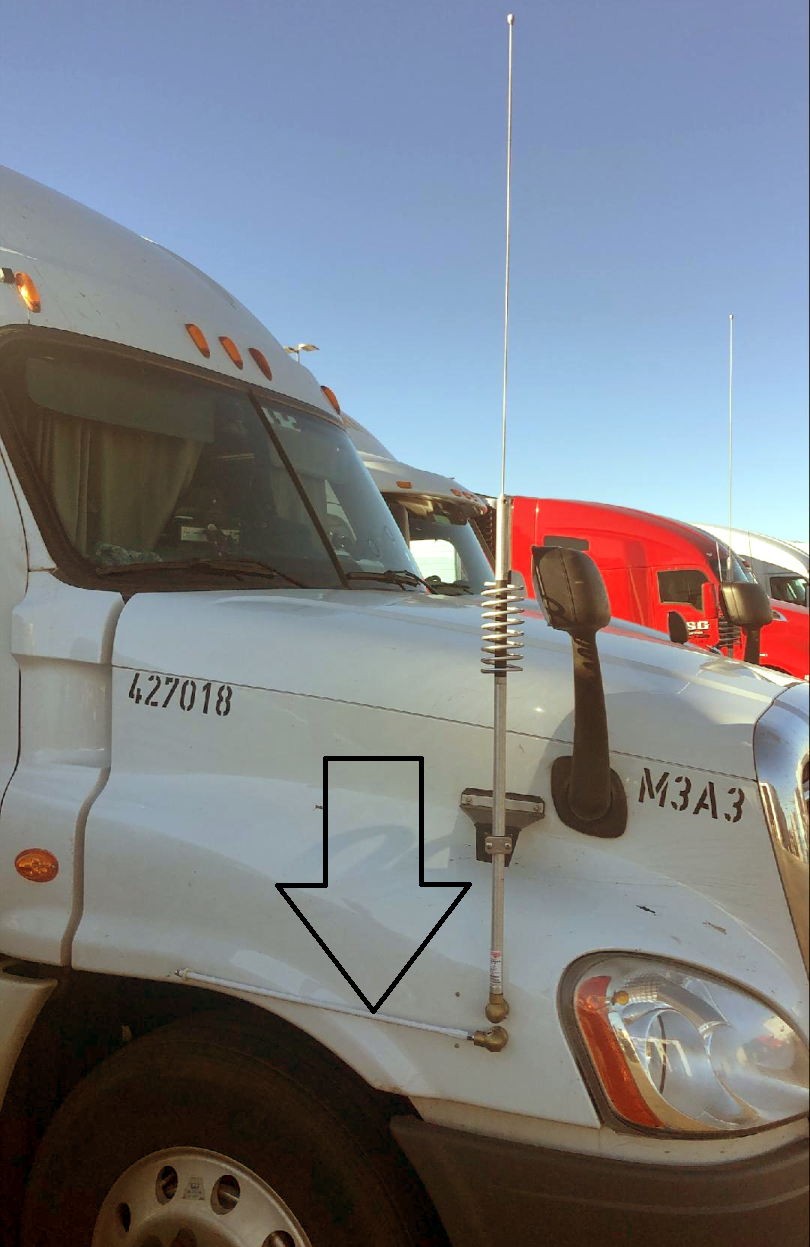
Here below is a brilliant use of 2
foot
Firesticks used as radials for a pair of co-phased Predator antennas
on a fiberglass Semi-tractor.
Figure 2
James Rellinger K5JPR 19Delta Transport, LLC Dallas, TX