The J-shaped antenna has its beginning back when
radios were used in gas filled balloons and rigid airships where there
was no possibility of a ground or dipole. The J shape is formed
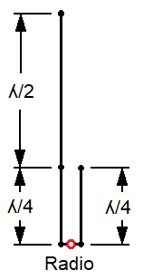
by a half-wave radiator end-fed by a quarter-wave matching section
connected to the radio. Related antennas are: Zepp (Zeppelin), J-pole, Half Square, Bobtail Curtain, End-Fed-Half-Wave.
The
length of a half-wave (ʎ/2) in the 6 meter band varies from 9.4 to 8.7
feet. The J-Antenna therefore will be in the range of 14 to 13
feet tall.
In this note I reveal how a little known characteristic of this antenna
can be used to make a 6 meter J-antenna ranging only 7 to 6 feet tall.
The Little Known Characteristic
From Figure 1 we see that a J-antenna resonates as two half waves on
the total length of the wire. By definition it is radiating on
the 2nd harmonic. The frequency of the 1st harmonic varies
from 1.8 to 1.9 and averages around 1.85 rather than 2 times higher in
frequency. This is due to elevation, velocity factor, wire separation and
end-effect.
Think of this 1st harmonic as resonating as a 6 meter, vertical half-wave dipole, fed off-center on one folded end.
We will use this characteristic for a half-size 6 meter antenna.
Figure 1: J-Antenna
Application for Half-Size
Calculating starting dimensions is simple. Using the desired 6
meter MHz, multiply by 1.85 to find the approximate frequency of the
1st harmonic. From this calculate 1 wave-length of wire.
Subtract the length of the separation and use the remainder to
calculate the � and � vertical lengths.
Build according to Figure 1. Insulated wire shortens by 1-2%.
Example: 50.5 MHz *
1.85 = 93.4 MHz or 1 Wave = 938/96 ≈10 feet. Subtract separation: 10 –
0.42 = 9.58 ft. Tall = 9.58 * 0.75 = 7.185
ft. Short = 9.58 *0.25 = 2.395 ft.
Model results give 51.0 MHz Frequency is too high = wire is too short.
Fine tune vertical wires to be longer by: 51.0 / 50.5 = 1.01 Separation (0.42) does not change.
New length is 9.58 * 1.01 = 9.676 ft. Tall =9.676 * 0.75 =
7.257 ft. Short = 9.676 * 0.25 = 2.419 ft.
Model results give 50.5 MHz at 1.45 SWR, Z=70.8 -j7.47 Ohms
Considerations
1. Separation between wires is not critical. Around 3 to 6
inches is good. The connecting wire is part of the radiating wire
and must be held constant length as other dimensions vary.
2. At
the feed-point add
a chokesuitable
for 50
to 100 MHz.. This
type of antenna is
notorious for common mode current.
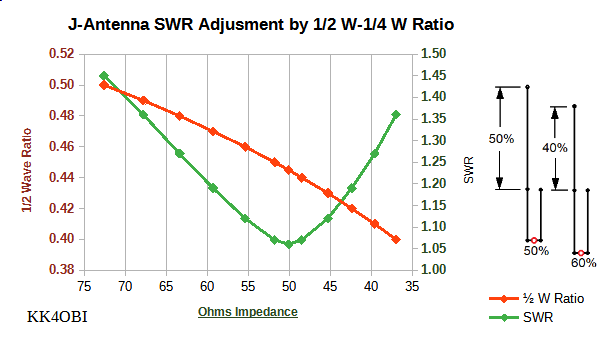
3. Impedance will be above 50 Ohms due to the off-center
feed. Fortunately impedance gradually goes down as the 50:to-50
top-bottom ratio of the 9.676 feet of wire is reduced towards 40-to-60.
See Figure 2.
Modeling says the SWR (green line) passes through a minimum around a
0.44 to 0.46 1/2 Wave Ratio (red line).
Figure 2: Ratio Tuning for SWR of the 1st Harmonic
SWR
fine tuning example
Start
with 44.5%for the top proportion(ʎ/2)
of the wire:9.676
*0.445
= 4.306
feet
The remainder is:
9.676
– 4.306
= 5.37
feet for the (ʎ/4)
matching section... or 2.685
feet per side.
New dimensions: Short = 2.685 ft. Tall =4.306+2.685 = 6.99 ft.
Model Results
10 feet over "real ground". #14 wire.
Gain: Typical of a J-antenna the radiation pattern is not
quite circular, 2.05 to 1.52 dBi as compared to a half-wave high
vertical dipole at 1.6 dBi.
4NEC2
Model “HALF-SIZE 6M J-ANT.
RATIO VERTICAL.NEC”
(The 4NEC2modeling program
is free at: https://www.qsl.net/4nec2/)
The model is plain text and
can be saved in *.NEC format.
To
run the model directly in 4NEC2, copy the
text between the lines and
paste into the Notepad
Editor. Ctrl+F1 or Main, Settings, Notepad Edit
========================================================================
CM This is a simple model of a
J-antenna
CM Feedpoint is midway between
elements.
CM
CM The half-size feature comes from
first optimizing "Har1" to hit the 50.5 MHz “Freq”
target...
CM Then optimizing "Ratio"
to adjust the top-bottom proportion for minimum SWR.
CM
CM The J-shape forms a 50.5 MHz
vertical dipole shortened by the bent end.
CM Feeding at the connecting wire
works much better than the J-Pole shorting method.
CM
CM KK4OBI Aug 2023
CE
SY Freq=50.5
SY Har1=92.74235
SY WL=938/Har1 ' One
Wave Length
SY hgh=10 'feed
point elevation feet
SY Sep=0.44 'separation between
elements (3) 0.44
SY Ratio=0.445 '0.4454
SY ResWire=1WL-sep 'Resonant wire
for verticals
SY Top=ResWire*Ratio 'Height of the
tall (1) element - 4.2341
SY Base=(ResWire-Top)/2 'Base (2) of
the tall element - to find mid point. 2.7282
SY IMBEDDED CALCS=2 'Go to: Geometry
(F3), View, Symbol Conversion
SY Height=Base+Top
SY TotWire=Top+Base+Sep+Base 'Total
length of the wire
GW 1 67 0 0 hgh+base 0 0 hgh+base+top #14 'Top
part of tall element
GW 2 41 0 0 hgh 0 0 hgh+base #14 'Base
part of tall element
GW 3 7 0 0 hgh sep 0 hgh #14 'Separation
between elements
GW 4 41 sep 0 hgh sep 0 hgh+base #14 'Short
element
GS 0 0 0.3048
GE 1
GN 2 0 0 0 14 6.e-3
EK
EX 0 3 50% 0 1 0 0 'Feed point
FR 0 0 0 0 freq 0
EN
========================================================================