KG6MVB's Tuner simulator for Icom 718
WARNING!
This page describes a modification that you plug in to your radio. Do this at your own risk! It's your choice to do this. I'm not forcing it on you. If you don't, hey, no hard feelings, but if you do and mess something up, don't blame me. This was designed and tested on an Icom 718 HF rig. This has also been reported to work on the IC-706, however there have been unconfirmed reports of trouble on the IC-7000. Circuits of this type have been reported to interfere with the temperature sensing circuit on the 7000, causing it to overheat and cook the finals! As I do not have a 7000, I can not confirm nor deny this, but you have been warned!
Let me start with this note. My original tuning circuit is a very simple circuit. It's a bit quirky. If you let the tuning time out, and the rig likes the swr, you will see tune on the display. You won't be able to run the tune again until you change frequency. If you have a mismatch however, it may run tune on your next transmit. It may also start tuning on power up, which is not good. On power up, you are putting 14 volts through 1000uF with small resistance directly into the CPU circuits (also not good). For all these reasons, I do not recommend my original circuit.
AB2TC published a much better circuit in the Yahoo! IC-718 Moderated discussion group. I have republished his circuit here (with permission). Although it is more complicated than mine, it is still a simple project. My parts cost was only around seven dollars, and my build time was under an hour. I am using his circuit, and it works as you would expect. It only tunes when you press the tune button, it never tunes on PTT or power up and you can repeat it at any time. It will stop when you press tune a second time, or after 20 seconds. I would recommend his circuit over mine. This is one of the great things about this hobby - hams helping each other.
AB2TC's Improved Tuner Simulator
Parts List:
(1) Molex 4 pin male connector with pins. Radio Shack 274-224
(1) RCA plug
(3) 27k resistors
(2) 12k resistors
(1) 470k resistor
(1) 0.022uF capacitor
(1) 0.1uF capacitor (see notes)
(2) NPN General purpose transistors. I used 2N2222
(1) Silicon switching diode. I used a 1N4148
(1) Case and perf board. I like the ones with the solder pads
(1) Short piece of 4 conductor cable (for Molex connector) - about 3 inches
(1) Short piece of 2 conductor cable (for RCA plug) - about 3 inches
Some notes on his circuit. I had to do a double take on the capacitor value. Typically, you don't see NF used. This translates to 0.022uF. Also, I would recommend adding a .1uF capacitor across the 14 volt power. Even though I did not have problems, I added one for good measure. It will help avoid problems if you have RF in the shack. My shack is clean, however I often operate portable, and out in the rough, who knows what you will have. It can't hurt to add it. Note - I added the cap after I took the pictures - that's why you don't see it. On the 718 the send control jack is an uncommitted relay contact to ground and this is perfectly safe with the circuit. On other rigs the similar purpose jack may have very different topolgies. Any stiff voltage appearing on this jack will destroy the base emitter junction of Q2 (actually with 0.022uF 5V is probably OK, but it will be rough on it). Any high voltage (tube rigs) certainly will be destructive.
At the time I built the tuner simulator my junk box was packed up and in storage (moving). I purchased everything new and only spent approx $7.00 US including the enclosure.
Setup:
In initial setup, tell the rig you have the ah4 tuner, turn off autotune and turn off ptt tune.
Operation:
Set the meter to swr first. When you press Tune, the rig will put out a low power carrier and display Tune (flashing) on the display. Tune your tuner. Press tune again to stop. If you let it run, it will time out at around 20 seconds.
I wrote down the settings for each band so I could pre-tune the rig, and just use this for touch up. Makes it faster, and you create less qrm.
Of course as always, don't be a lid. Don't tune up on top of someone else, and remember to id when done, as you are transmitting.
Here are some pictures of the completed project.
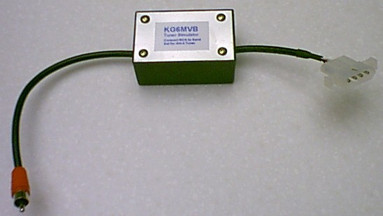
Completed project.
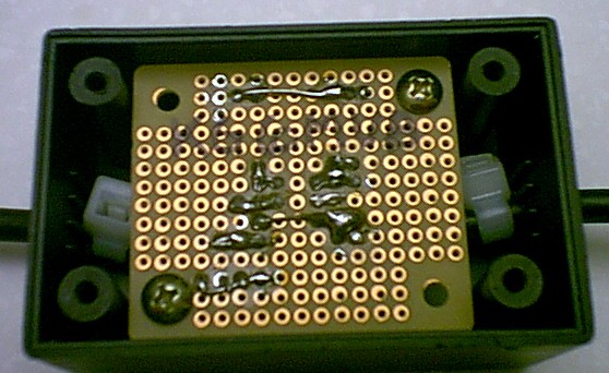
Solder side.
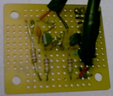
Component side.
I would recommend AB2TC's circuit over mine. My original circuit is published below.
KG6MVB's Original tuner simulator (not recommended)
Parts List:
(1) Molex 4 pin male connector with pins. Radio Shack 274-224
(1) 1000uF capacitor
(1) 100k resistor
What it does:
This enables the Tune button on the front of the rig. This turns on a 10 watt carrier for approximately 10 seconds, regardless of the power and mode settings on your rig.
Why do it:
Convenience. The old method was to switch to cw mode, drop power, key down, tune, restore power, change back to original mode. Now I just push a button, tune, push button again.
Description and Operation:
Connector is a standard molex power connector. Radio Shack even sells this one. Cap is 1000uF, and resistance is 100k (not critical). If you look at my pictures, you will see I used two resistors in series. This is not necessary; I just used what I had in the
junkbox (mine is 94k, two 47k in series). Cap and resistor are parallel. Pins 1 and 2 of connector are shorted together, with - side of cap and one side of resistor connecting to them (counting from the side with the pointed end). + side of cap and other side of resistor connect to pin 3. No connection to pin 4. Tell the rig you have the ah4 tuner, but turn off autotune and ptt tune.
Set the meter to swr first. When you press tune, it gives you about 10 seconds of low power carrier. You can stop it by hitting tune again. It's a bit quirky. If you let it finish, and it likes the swr, you will see tune on the display, and it won't run again until you change frequency. Remember, the rig thinks an autotuner is there.
I wrote down the settings for each band so I could pre-tune the rig, and just use this for touch up. Makes it faster, and you create less qrm.
Of course as always, don't be a lid. Don't tune up on top of someone else, and remember to id when done, as you are transmitting.
How it works:
When you press the tune button, the radio applies 14 volts to the connector, to start the tuner. This charges the capacitor. The capacitor immediately starts to discharge through the resistor. The radio "sees" a voltage at the connector and thinks the tuner is hard at work. Once the capacitor has discharged to a low enough voltage, the radio thinks it is done, and turns off the carrier.
Armed with this knowledge, you should see that a bigger resistor or capacitor would give you more time, as the discharge cycle will be longer, and smaller ones would give you less time.
73 de KG6MVB
Tom
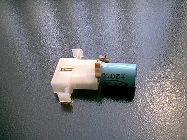
Here it is. Yes, it really is that simple.
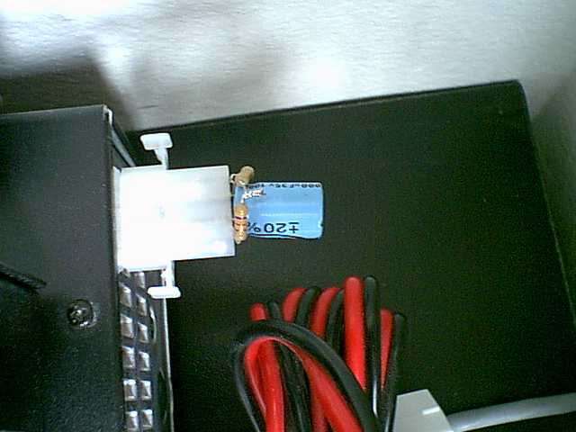
Here is the tuner, on the radio.
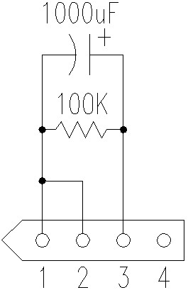
Schematic Diagram. Couldn't be much simpler!
Back to my main page
This page was updated on October 3, 2006.