|
|
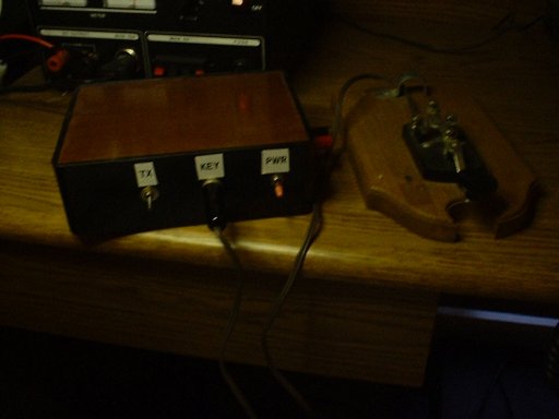
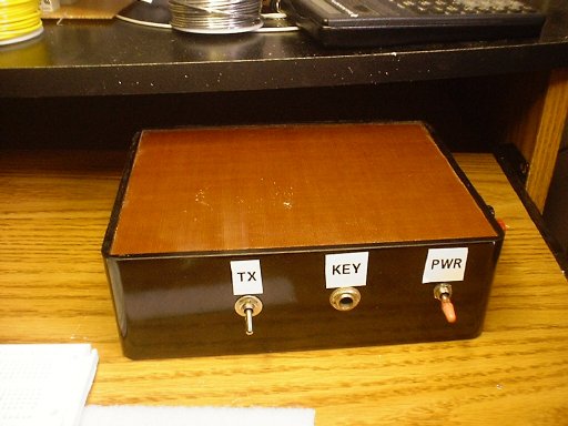
Now here is an attractive home made transmitter. Obviously CW mode. I'm not smart enough to come up with a design for side band. Shucks, most of this rig was pieces of other peoples designs, but then again aren't they all? |
| Lets turn up the lights and see just what we have in front
of us. There doesn't seem to be any marking on this unit that tells us
which band it operates on. No need to. If your on this page then you
already know that this is a 1750 meter transmitter. You heard right
1750 meters. No license is required to operate in this band so long as
you follow the FCC's
part 15 requirements.
On the front panel we have two switches and a plug. These are clearly labeled. The only switch that arouses any sort of questions would be the TX switch. This simply keys up the transmitter. I placed it there for testing purposes, and figured "Why take it out?" |
 |
|
|
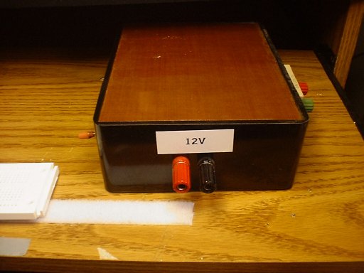
Along the side I placed the power connectors. 12 volts seems to work best and puts out the most power, but anything between 8 and 15 volts will work just fine. |
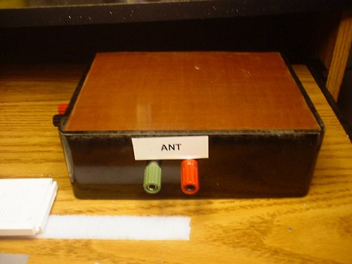
| Spinning the unit around to the back we see the antenna connecters. At the moment this unit is looking for a 50 ohm load. This will be explained in a little more detail at the bottom. |
|
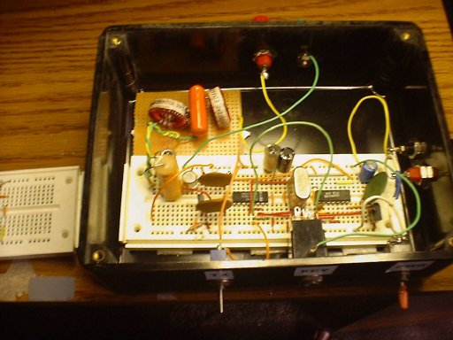 |
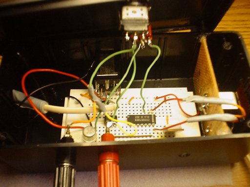
Enough already with this cosmetic hub-bub lets look under the hood. Personally I feel that this is one of my more tidy projects. A person deep into VHF/UHF would think that I am crazy for using a Radio Shack experimenters board for this unit. But hey, this far down in the radio basement, lead length isn't too much of a problem. What we have here is a simple oscillator, amplifier, and low pass filter, all wrapped up neatly in this box. |
| First we'll look at the oscillator portion. Basically we have a crystal oscillator. The crystal has a natural frequency of 1.8432 Mhz. I'm using a 4001 Hex Inverter. One of the gates helps the oscillator get going and two of the other gates are used to buffer this signal. I pumped this signal into a 4017 counter (I think), and this divides the frequency by 10 giving us 184.32Khz out. I used the remaining gate of the 4001 Hex inverter as a buffer going to the amplifier stage. This portion of the circuit was featured some time ago in a Radio Electronics magazine article. I managed to get this article when the photocopies at the library were still free. Lets move on to the amplifier portion of the circuit. | 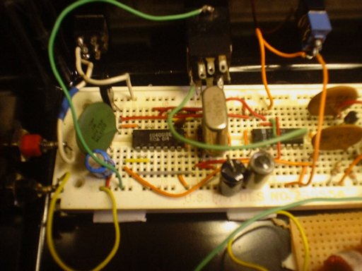 |
 |
Before I describe anymore of this circuit, let me say that
this entire project was inspired by K0LR. It was from his web page that
most of this is from. This guy really knows what he is doing when it
comes to radio. Outlines, diagrams and computer interface ideas of the remaining pieces
of the transmitter in this
article are available at his website.
The amplifier is a complementary pair using a 2N2222 and a 2N2907. This is an excellent and cost effective amplifier. The problem that we have at this point, and you'll know this if you have ever built an oscillator using these types of parts, is that the output so far is a square wave. A messy, sloppy square wave chop FULL of harmonics. |
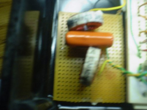
| A couple of coils of the same value and a capacitor
arranged in a T fashion will choke them pesky harmonics out of our
signal. I was truly amazed at the results of this little filter. The
waveform became PURELY sinusoidal at the output. This little filter
straightens things up at the output, so the transmitter looks for a 50
ohm load. Depending on you antenna arrangement this filter can actually be
discarded if you were to use a
tuned loop. At this point the transmitter is complete. You can fire it
up, plug in a key and prey you have an effective antenna and it will work
nicely.
But wait! I said 1750 meter BEACON. Well the article is not over yet. There is a separate unit that I designed and built on my own. One of the few things that I HAVE designed and built on my own that works.
|
|
|
|
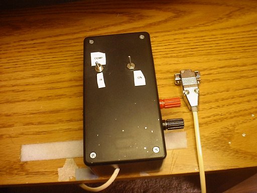
Here is the unit that turns the transmitter into a beacon. Nothing special about its appearance. Just a black box with a few switches. One switch is for power and the other is for switching between a computer serial interface and a Infra-red remote control interface. |
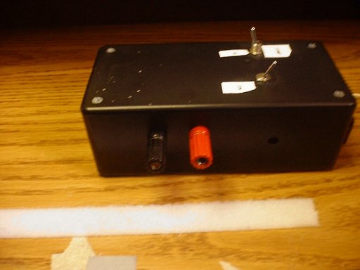
| Looking at one side of this unit we see the obvious power connections. This little guys runs on 5 volts, but I regulated the circuit so any voltage between 5 and 12 volts will work fine. |
|
|
|
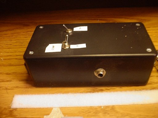
Spinning the box 180 degrees reveals a plug that is the interface for the transmitter's key. This is where all the beacon magic comes out. |
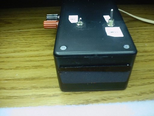
| Mmmmm, This is my favorite part of this unit, the infra-red interface. Here we see a red window allowing Infra-red light to come in. Not just any infra-red light will trigger it. The sensor is calibrated to have a 40Khz band pass. All standard remote controls use this type of logic. I would assume its used to cut out unwanted signals generated by a host of different sources. I have actually transmitted infra-red remote signals over this thing. This wasn't a feature I put in merely to be the coolest kid on the block. I thought that since antenna restrictions are so tough in this band. I would have to mount the transmitter and beacon unit at the base of the antenna. This way I can trigger the transmitter remotely. |
|
 |
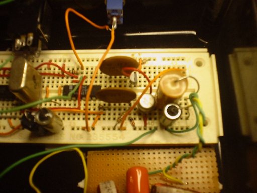
Opening the top of this unit can sometimes be tricky. If
you have a sharp eye, you'll note that the switch closest to the camera
has a wire missing. When I opened the box up for a picture, my poor
soldering ability got the best of me and the wire snapped off.
First take a look to the right side of the unit, with the vertically mounted PC board. The little metallic thing soldered to it is the infra-red sensor, these are available at Radio Shack at a modest cost, and if you have some free time, pick one up to play with. I think they are really neat. On to the circuit board to the left. Yup, its another one of those Radio Shack experimenter boards. These things are great. Since there is no soldering you never have to choke on the solder fumes. When using a serial cable connected to a computer as a transmitter trigger, you have to be very cautious of all the noise that the computer generates as a result of its processing. I eliminated this noise source by using an Opto-coupler. The little chip that can barely be seen behind the red power post is actually an LED and a light sensitive device all in one package. This is a great scheme, no noise all serial signal. The infra-red sensor acts a lot like a photo transistor, in the switching fashion. Too bad that the signal that comes from this is so small. Once again by using a couple of 4001 Hex inverter gates as a buffer, our minute signal becomes a booming 5 volt square wave. The triggering of the transmitter is performed by the fat juicy transistor sitting between the two power poles. What value is it? Who knows. I just have a big bag of these guys that were given to me when I worked as a tech for the cable company oh so many years ago.
|
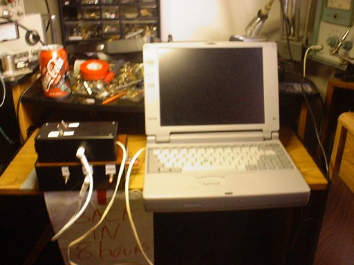
| Here we see the finished product. Transmitter and computer
interface set up nicely on top of one another and an old P75 Toshiba
laptop. At this point you might all be wondering about the computer
interface that I have used. Well the serial cable only actually uses two
pins on the serial port AKA RS-232 interface. One of the standard pins
on a computer's serial port is the DTR pin, or Data Terminal Ready pin.
This is a pin that synchronizes data and lets the other computer know
that it is ready to receive info. By switching this pin on and off via
software, you can create a signal that can key a transmitter.
I did NOT write the software used for this. This software is available at K0RL's web site. |
 |
|
|
Some might find it crazy. Using a p75 laptop running in dos to trigger a single pin to key up a transmitter using less then one watt of power. It might seem even more crazy to be sitting around listening to static for hours on end hoping that you might actually be able to hear this beacon over a hundred miles away. Personally I feel that there is a fine line between being crazy and liking a true challenge. I encourage all readers of this article to take the time to sort through the Long Wave Club of America's website. In it you'll see the accounts of several dedicated individuals that devote there time to doing just that. With an amazing amount of success as well. This article is dedicated to them and others daring to push the envelope of weak signal work. |