Welcome to my newly created QRP kit page. This page was created for one purpose, to share a kit building experience from the "rank amateur" perspective. Although I’ve seen, and read many web pages regarding the construction of various QRP kits, most (if not all) of the pages were authored by obviously very experienced electronic "guru’s". Although this type of critique is very informative, is does little to help the novice builder decide which kit to build, or even if a kit is within their abilities. This page is specifically designed for that purpose (at least until I’ve built enough that I begin to sound like those other "gurus"….hi hi) First, a little bit of background on me. I am NOT an electronics expert, in fact, I’ve not even soldered a PCB before this first kit! I did practice a bit on a scrap board and about $2 worth of resistors and stuff. (there is a great series of articles on-line that describe soldering and kit building in general authored by N1FN and available here)
For my first kit, I was undecided between the Oak Hills Research OHR-100A, the Small Wonder Labs SW-40, the Small Wonder Labs DSW, and the Wilderness Radio ????. All of the kits had their pros and cons, but I finally decided on the Oak Hills Research OHR-100A, and a review or two on eHam stated that this would make a good first kit. It has a full 5-watt output (variable 0-5 watts), 70 kHz of bandwidth, and a full 1 kHz RIT. The Small Wonder Labs DSW came real close due to its full band coverage, audible frequency readout, and small package. I decided against it for a first kit as reviews had mentioned it might not have been a good "first kit". (a 20 meter version might be my SECOND kit though.....standby for further.........)
No bad news here, I ordered the OHR-100A "chambered" in 40 meters via the secure Internet website on a Friday. By Thursday, I had the kit in my hands.
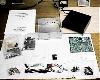
The kit was well packaged, with the metal cabinet well protected from scratches. Several small ziplock baggies contained the various components, with easily confused parts packaged and labeled separately. A good, high quality xerox copy of the instructions were included. The instructions seem well written (again from a novice perspective) and the PCB board layout view was very easy to read, and a full schematic was included for those that want (need??) one. A parts list is also included with drawings of the various components, a very nice touch for those like me who didn’t know the visual difference between a monolithic and an electrolytic capacitor.


![]()
As per the instructions, an inventory was performed, during which all components were identified and sorted. The result, 1 extra resistor, 1 undocumented part substitution, and 1 missing setscrew on the main frequency select knob. An email was sent to Marshall Emm asking about the part substitution, and informing of the missing set screw. An immediate emailed response was received, and Marshall apologized and assured me the setscrew would be in the mail to me ASAP. The part substitution was a PC mounted pot, which was blue in color (not white as described in the parts list), and the markings on the unit were different. Marshall informed me that his suppler had run out of the white ones, and apologized again. (as if an apology was necessary for this) Again, the well documented parts list (with drawings and any component markings) made the parts identification very easy for the amateur such as me with no idea what a rectifying transistor should look like.


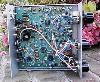
OK here we go! I plugged in my 15-watt soldering iron and went to work. The nicely silk-screened board with the part identification numbers, the solder masked back, and the plated through holes made assembly a breeze. Not to mention the good instructions again. I quite certain that an experienced kit builder would find the level of instruction annoying, but as a virgin kit builder, I appreciated every word. The assembly went quick, but I resisted temptation to fly through it and took my time making sure every component was well soldered and placed correctly.
Winding cores was obviously new to me too. The documentation was well written and clear. The actual winding wasn’t that bad! Just took some patience and time to count the turns correctly. Mounting of the cores was another matter. Apparently, I got in a rush and didn’t tin the leads very well. This may have been the hardest part of the kit for me. The instructions told how to do this, but I guess I underestimated the time it takes to tin the lead. I held the iron against the colored magnet wire, and the colored coating melted away quickly. I applied the solder and it stuck (kinda) but obviously not well enough. When mounting these cores, I discovered every joint had a bit of a "dimple" where the lead poked through the solder. This just wasn’t right. But, being the fool that I am (and rushing a bit) I made every coil connection like this. Later (see Smoke Test) when I had some problems on transmit, I removed every core (9 total) and re-tinned and remounted these cores. Made me wish I had done it correctly the first time!
Assembly in the cabinet was a breeze due to the Molex connectors. The cabinet was well made and the fit and finish were perfect. Damn the unit looks good.


The moment I’ve waited for. All connections were checked, the portable battery was charged, the unit was assembled (less the top cover of course) and power was applied to the unit. I left the unit on for 10 seconds or so and looked, listened, and smelt. Nothing wrong here. I re-applied power and left it on. The background static was good news. The unit was working on the first try…….or was it? I played around a bit with the pots to achieve a good tone and sidetone, easy! I fired up my main station transceiver and sent a 10-watt signal on 7030 kHz. I tuned around on the OHR-100 and finally found it with the dial reading 7080 kHz. Guess we need some alignment here! Now for the "other" half. I plugged in an antenna and set the OHR to transmit at midrange power levels. I keyed down and tried to find the signal on my main unit. Couldn’t find it. I plugged in a power meter and found I wasn’t radiating any RF. Hmmm. I re-checked all my external connections and didn’t find anything wrong, so I ran my VOM in series with the power lead and found that the unit drew about 90 mA of power on receive, and only 118 mA on transmit (spec’s called for about 80 and 850). I most defiantly wasn’t transmitting. I checked all the components and joints again, no real problem was found, although a couple of weak looking joints were found and corrected. I checked the placement of everything, again, no mistakes found. An email was fired off to Marshall who again immediacy responded. He suggested checking the coils, transistors and trim caps. (this is where I removed and replaced every coil and re-tinned/re-soldered). Marshall also let me know that due to the drawing of 118 mA of power on transmit, he felt that the circuit was working to a point, perhaps up to the final. The next few days were spent anxiously checking various components, joints and everything in between. Absolutely nothing of any significance was found. The transistors in the transmit circuit were removed and I attempted to check them with my VOM. They identified OK as PnP, confirmed the location of the ECB (emitter, collector, and base) but would not give me a numeric reading. (I don't know if these types of transistors SHOULD give a reading on my meter). These components were not easy to remove, in fact, I did damage to the solder track / pad on one leg upon removal. I replaced the transistors on the board and checked again. Still no x-mit! The decision to send it in for evaluation and repair was made. Marshall stated in one of his emails that if I were to send it in, to please enclose the "standard alignment" fee of $45. That was fair enough, obviously, I was going to pay that anyway for a "real" alignment. I also enclosed a letter authorizing resonable repair fees with a note to please notify me in advance. As a side note, I also begged in the letter to please let me know what was found! Curiousity is killing me!
The unit was mail on Monday, and by Thurday, Mr. Emm called me to tell me he had received the unit and had already run a few tests on it. He said the VFO coil was about 400 KHz above what it should be, and coupled with the fact that I had a "dog-leg" bend in the antenna connection wire, I was probably filtering out the RF the unit was producing! (I left the antenna wire intentionally long and bent it for testing purposes. My intent was to cut the wire shorter after testing and make a nice straight "neat" connection) I had no idea that this bend here would cause a reactence problem! Friday, Marshall e-mailed me and let me know he had just finished a QSO with a VA station using MY RADIO and everything looked great. He said it put out 5.2 watts and was rock steady in frequency. He mentioned he had to place an additional turn on the VFO coil to get it on frequency and had repaired a broken PCB track where I had removed the final transistor for inspection. He had aligned the unit for 7000 KHz up, and had trimmed the caps for a 700 Hz sidetone and a 700 Hz offset for "sound alike" zero beat use.
Marshall then very tactfully gave me a few construction tips. He said that the joints looked good with no cold or dry joints, no bridges, but I was a little shy on solder usage. He suggested I use a bit more solder on the joints, and he also mentioned that I should have placed the capacitors down on the board a bit further. He said these issues weren't causing any problems, and should not repaired unless a problem developed. Just friendly advice for next time! The comments were very well received and appreciated.
One simply could not ask for a better job in customer technical support and repair. The work was done FAST and communication between client and customer was prompt and continuous. It's nice to know that if problem arise, they can be taken care of promptly and effienctly! Oh yeah, there was no charge for the repair work (re-winding of a coil, repairing of a broken track, cleaning up of the antenna connection wire). Just the $45 for alignment & shipping (combined)
I powered the unit up, connected it to my Hustler, 6BTV ground mounted vertical antenna, and started answering CQ's. Made five quick contacts that first night with MI, PA, TX & NY with most RST reports in the 559 catagory. (had a 349 from TX and a 589 from NY). All output was at 5 watts (hey, give me a break, I'm new to this QRP stuff) I had to reduce the sidetone volume a bit, and adjust the VFO knob just a bit to get it on frequency, but other than that, it was plug & play.
The receiver is almost too good in this unit. I was hearing signals (& QRM) from all over! I really see the need for the bandwidth knob on this baby. One can zero beat a station and use the bandwidth control to filter out most of the side garbage. When I e-mailed Marshall to let him know that the rig was received and working correctly, I mentioned this. He informed me that he finds it useful to turn down the RF Gain to about 75%, adjust the AF to a comfortable level, and use the RF Gain as the volume control, leaving the Bandwidth in about the 60% range. I'll certainly give this a try next time.
Bottom line, was a quick relativly simple project that performes like a champ. Even if one encounters problems during construction, Mr. Emm will bend over backwards to help you. He is extremely quick on his email, in fact, most replies were within an hour or two! Don't hesitate building this one as your first radio!
If you have any questions, please don't hesitate asking me @ [email protected]