Let me begin by stating that a J-Pole antenna, is like all open end antennas, a form of Di-Pole!
I realize this statement will confuse and maybe even offend some
people, but it's true never the less.
As you can see from the illustration below, a J-Pole, is only a
Di-Pole, that has been folded 3/4 of the way down and fed off center.
Lets address some of the other antennas while we are on the subject.

Which looks more like this.

A yaggi antenna, is only a di-pole, with a reflector and some directors attached.
The vertical on your car, is one half di-pole, with the car body representing the other half.

An end fed antenna, is one end of the di-pole, with the ground serving
as the other half.
The same situation, is true, with a vertical antenna.
The radiator, is one half of the di-pole and the counterpoise or ground
plane, is the other.
Now that we've got that out of the way, let's get on with the J-Pole.
Some parts you will need!
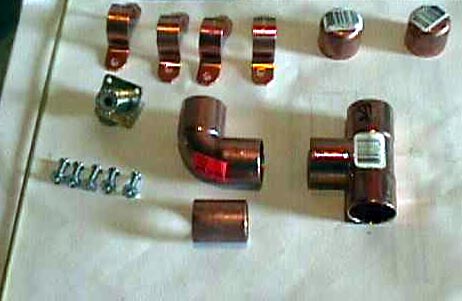
Materials List
10' 1/2" Copper Water Pipe
1 "T"
1 "Elbow"
2 End caps
1 SO-239 Connector
3 Machine Screws with Nuts
4 1/2" Pipe Straps

A=Benz-O-Matic propane torch; B=Lead-Free solder; C=Tape measure:
D=Tubing cutter; E=Sharpie marking pen;
F=Solder Paste; G=1/2 inch copper caps; H=Hardcopy of the
above drawing; I=Wet Towel; J=PreCut, ready to assemble parts of the 2
meter J-Pole.

Dimensions!
A. Long 57.96:
B. short 19.20"
C. feed point 1.2"
D. spacing 1.8"
Cut to dimension!
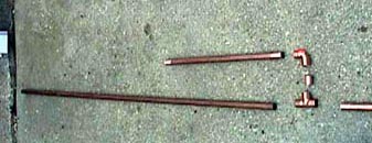
Now, sweat solder the 57.96" piece to the "T" connector.
Solder the 19.2" piece
to the elbow connector.
Next, insert the 1.8 inch piece between the
elbow and "T" connectors.
Make SURE the 57.96" and 19.2" piece are parallel.
The elbow and the "T" should be butted up together.
Be sure that the "T" to Elbow connection is
soldered well, as this is a major stress point.
Finally, go ahead and solder the end caps
on the pipes. This keeps water from collecting inside of the pipes, which
could freeze and burst the pipes in the winter.
Now solder that left over piece of copper to the bottom of the "T"
for
a mounting
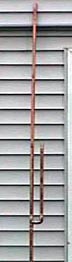
mast. The length of the mast is irrelevant, so cut it down to suite your
needs. Your J-Pole should look something like the picture show
here on the right. Notice the
short radiator is parallel and equidistant from the long radiator

One of the snafus of the J-Pole, has always been the complaint that they were hard to tune!
The biggest reason for this, seems to be the problem of using a fixed
feed point.
To alleviate that, I have tried to come up with a way to make the feed
point adjustable.
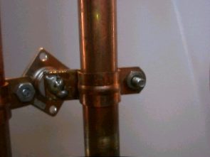
The first thing you need to do is flatten out two of the 1/2" straps.
Use a vice or a
hammer
and get these as flat as you can.
Now, line
up the holes of one of the unflattened straps to a flattened strap and
bolt
them together.
Solder the unbolted sides of the straps together. Do this for the other
set of
straps as well. The goal of this is to make a "sliding" matching section
so we can
adjust
the SWR or the antenna.
Go ahead and mount the 2 sliding straps on the short and long sections
of the J-Pole. Notice how the
flattened straps are facing one another on the inside of the "J".
We are now going to mount the SO-239 jack to the J-Pole. We do this
by bolting the SO-239 to the strap
on the shorter radiator through the hole already provided in the strap.
You may need to trim a little of the copper off of the strap to allow
the SO-239 hole to line up with the
strap hole. Go ahead tighten the SO-239 to the strap.

Note!
I've recently changed the way the SO-239 jack is connected to the
feedpoint.
This makes for a more rigid and better looking package.
I've turned the straps to face each other, shortened them, and redrilled
the holes.
I then bolted the SO-239 jack to the short side.

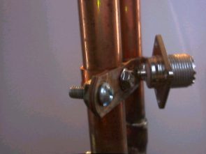
I then soldered the center conductor of the jack, to the strap from the long side.
Generally I will have an SWR of 1.5 or less over all of the 2 meter band.
Now, give yourself a BIG pat on the back
for doing such a great job, and doing it yourself! This antenna rivals
the popular Cushcraft Ringo, which retails for around $45.00. Total cost
of this antenna is around $15.00 !