SW40+ VFO
A 3 Mhz. oscillator supplies a sine-wave to both receive mixer and transmit mixer. This note describes how Q2, a Colpitts oscillator is biased, how it begins to oscillate, and discusses some of the component selection. PSPICE is employed to illustrate circuit operation. The coupling circuits into the two mixers are described as well.
Biasing
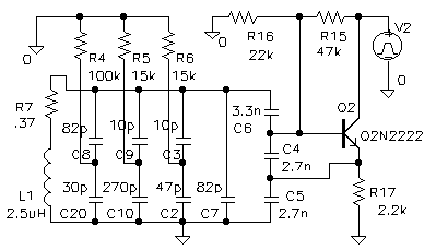
Only three resistors are involved in the biasing of Q2: R15(47k), R16(22k), and R17(2.2k). Q2's base-bias point is set by the resistor voltage divider R15, R16. From the 7.4 volt collector supply, you'd expect the base voltage to be 7.4*(22)/(22+47) volts or 2.35v. Instead, Dave shows it to measure 3V (pg.19 of the manual) - why the difference? The answer is that Q2 is oscillating. It is actually operating in a very non-linear way. Should you prevent oscillations (by shorting out L1 with a short jumper), you'd find that the base voltage would settle much closer to the calculated 2.35 volts.

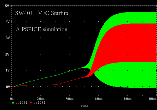
In a PSPICE simulation, Q2 was started initially with its collector supply at zero volts. It was then raised up quickly to 7.4 volts. The base and emitter voltages were plotted against time (with zero seconds corresponding to the moment that the collector supply was raised). The base voltage starts at zero volts because C4(2700pf), C5(2700pf) and C6(3300pf), are all discharged to zero volts. These capacitors all start to charge through the base-bias resistors. About 30 microseconds later, Q2's base rises to +0.6v and Q2 now begins to conduct current from collector to emitter. The emitter current charges C5(2700pf) slightly faster, and C4 doesn't charge much more because the base-to-emitter voltage track together (a 0.6 volt difference).

Somewhere between 35us. and 45us. Q2 starts to oscillate at 3Mhz. The amplitude starts very small from random noise. All the while, the capacitors continue to charge. The 3Mhz. amplitude builds quickly, because Q2 has a lot of gain and pumps up the resonant circuit a little more cycle- by-cycle.
At some time around 50 us., the oscillating amplitude has grown so large that Q2 begins to operate non-linearly. Up until this time, Q2 has been conducting current from collector to emitter all the time. Now however, on the bottom peaks of the oscillation cycle emitter current zeroes-out. For the fraction of the oscillatory cycle where emitter current is zero, Q2 is not contributing any current to build the amplitude higher.
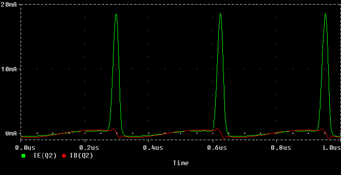
Between 50us. and 80us. Q2's emitter current shifts from a more-or- less sinusoidal waveshape to a pulse waveshape. The fraction of a cycle where Q2's emitter current is zero grows longer and longer. But Q2 still conducts enough (and has enough gain) to continue to add to the oscillation amplitude. So amplitude still builds, but at a slower rate.
Now we come to a fine balancing act. Q2 is cut-off for most of the 3Mhz. sine-wave cycle. For the short time it is conducting, it contributes enough of an emitter-current "pulse" to maintain the oscillation amplitude. Here, the energy lost every cycle (dissipated in lossy components, and delivered to the two mixers) is exactly replaced by the emitter current pulse.

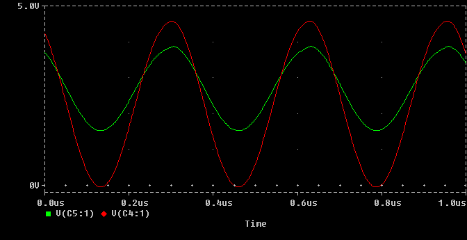
After about 80 us., this balancing act is in equilibrium. According to the PSPICE simulation, the emitter conducts only 14% of the time, at the positive peak of the AC waveform (on the base). The rest of the time Q2 is off - very little current flows either into the base, or between collector and emitter. While the emitter current looks like a string of short, sharp "spikes", the base voltage and the resonant voltage at L1 are clean sinusoidal waveshapes.

Which components form the 3MHz. resonant circuit? The only inductance in the circuit is L1 - it is the inductive reactance of the resonant circuit. The associated capacitive reactance is distributed among capacitors C2 to C10, plus the capacitive reactance of the varactor, D1. Much of the resonant current flows through C4(2700pf), C5(2700pf) and C6(3300pf). The reactances of the other capacitors are relatively higher, and they contribute less to the resonant energy.
L1 has about 2.5uH inductance. To resonate at 3 Mhz. a parallel capacitance of 1126 pF is required. To get to 3.04Mhz, a parallel capacitance of 1096 pF is required. The varactor diode must supply the difference of 30 pF.
Dave "taps-off" some energy of the resonant circuit to feed 3MHz. signals into mixer U1 and mixer U5. He does so with a capacitive voltage divider. C3(10pf) and C2(47pf) feed about 1v p-p into the U1, the receive mixer. The RF voltage across C2 will have a sinusoidal waveshape. This voltage divider allows U1's internal biasing to set the DC voltage point of its oscillator input, without disturbing Q2's own DC bias setup.
U5 (the transmit mixer) requires a much smaller 3Mhz. signal, because it is injected into the high-gain port rather than the oscillator port (as is done for U1). The small reactance of C10(270pf) only allows 0.2v p-p into U5.