by Glen Leinweber VE3DNL
The SW-40+ radio employs three of these chips: one to heterodyne the incoming small-signal (7MHz.) RF down to the I.F. frequency of 4.0 Mhz., another to heterodyne the 4.0 MHz. I.F. down to audio, and another to heterodyne the VFO frequency of 3.0 MHz. up to 7 MHz. for the transmitting amplifier.
This note uses a PSPICE simulation to illustrate the mixing function of this chip. As an example, the transmitting mixer is examined to show how the 3.0 MHz. VFO is mixed with 4.0 Mhz. to get the desired 7.0 Mhz signal.
The term "heterodyne" refers to the mixing function, where two different frequencies are combined in a non-linear way to generate an output waveform of a different frequency. Keep in mind that the process is non- linear: there is no way to linearly add two frequencies to get a third.
An audio "mixer" is an entirely different animal: it simply adds signals together linearly. If it did output other frequencies, an audio mixer would be considered faulty, and in need of repair.
In the case of U5 (a SE612 chip), one sinewave input signal from the VFO at 3MHz. comes into pin 2, while the chip generates the other input signal at 4MHz. internally. The output waveform is available at pin 4 and/or pin 5. An internal Colpitts crystal oscillator generates the 4.0 Mhz sinewave (the crystal oscillator connections involve pin 6 and pin 7).
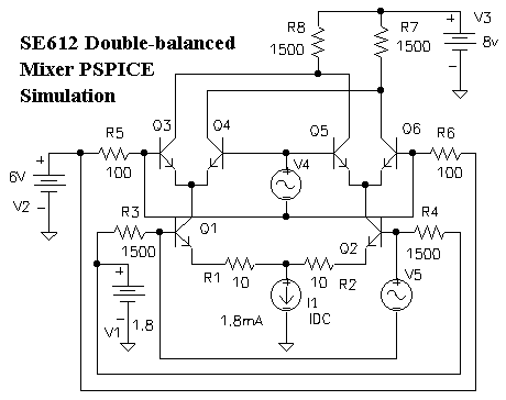
The heart of the mixer uses a circuit known as a Gilbert Cell. The output of this circuit is taken from R7 and/or R8. Inputs are represented as voltage sources V4 and V5:

A simple Gilbert Cell requires six identical transistors. Q1 and Q2 accept one of the mixer's input - in our case 3Mhz. from the VFO. The upper four transistors accept the other mixer input - in our case it is from the internal 4 MHz. Colpitts oscillator connected to pins 6.7.
V4 represents a 4 MHz. voltage source, simulating the Colpitts crystal oscillator connected thru SE612 pins 6, 7. V5 represents a 3 MHz. voltage source, simulating the 3MHz. input from the VFO. I1 is a DC current source, inside the SE612. If V5 were zero amplitude, half of I1's current would flow into Q1's emitter, and half into Q2. V5's input voltage unbalances current so that it flip-flops back and forth between the two transistors at a 3MHz. rate. Another way of looking at it is that Q1 and Q2's collector currents have equal amplitude, but opposite phase.
The real mixing action occurs at Q3, Q4, Q5, and Q6. The 4 MHz. signal drives the bases of these four transistors. Their collectors connect directly to SE612 output pins 4 and 5. Two internal 1500 ohm resistors provide a path to the +7.5v power supply. Notice how their collectors are cross-coupled together - part of the magic of double-balancing.
A simplifying assumption will show how mixing works: think of Q3, Q4, Q5 and Q6 as switches. In our case, Q3 and Q5 are "closed" when Q4 and Q6 are "open". Then the role reverses, with Q3 and Q5 "open" while Q4 and Q6 are "closed". The switching flip-flops back and forth at a rate determined by the 4 MHz. oscillator: each switch is "open" for 125ns., and "closed" for 125ns.
These switches direct the 3MHz. AC currents from Q1 and Q2 to the output pins, half the time to one, half the time to the other. The simple switching action described above is a VERY non-linear process, throwing chunks of the 3MHz. signals to one output or the other. The math is rather nasty, but in this process, other frequencies appear that are not simply harmonics of either the 3MHz. or 4MHz. input signals. We are entirely interested in one of these: at 7 Mhz. All others are unwanted.
A superb feature of the Gilbert-cell mixer is that neither 3 Mhz. nor 4 Mhz. signals appear at the output, provided that switching action is seamless, and the 3 Mhz. signals at Q1 and Q2 collectors are properly balanced. Ideally, only two frequency components will appear at the output: one at the difference frequency ( 4MHz - 3MHz = 1MHz) and one at the sum (4MHz + 3MHz = 7 MHz). That's the best we can hope for. Usually, these two dominate over a mess of other mixing products of lower amplitude.
The mixer still performs its task if Q3, Q4, Q5 and Q6 DON'T act as switches. Output will be smaller, but all we really require of these four transistors is that they direct more current during their 125ns. "window" and less during the alternalte 125ns. "window".
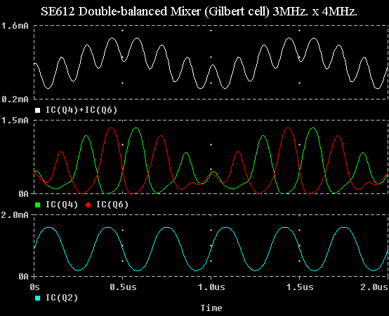
Now let's look at the PSPICE simulation, showing two microseconds of the Gilbert-cell mixing action. Only currents of one branch of the cell are shown for simplicity. You can see that Q2's collector current is almost a sinewave (the peaks are compressed a little) of 3MHz(bottom).

You can't easily see much 3MHz. waveshapes at Q4 or Q6(middle), but the 4MHz. waveform is quite apparent, as is the longer 1MHz. wave. Note that Q4 and Q6 waveforms bottom out at zero current. These transistors are operating partly into the "switching" region. Even so, the combined collector waveform looks surprisingly good. Isn't it marvelous how when the collector currents of Q4 and Q6 are combined, 3MHz. and 4 MHz. dissapear(top)? A really close, critical look at the output (top) will reveal some waveform compression. The output waveshape appears to be a combination of 1MHz. and 7 Mhz. sinewaves. The other output would appear similar, but out of phase. These output currents are translated directly into voltages by the 1500-ohm collector load resistors.
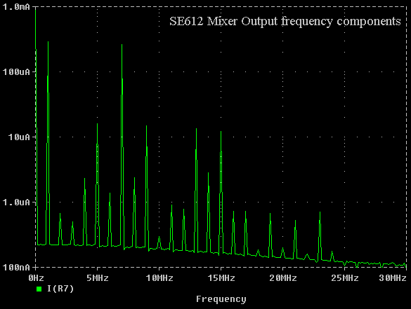
"Get OUT", you say, "there's nothing else there besides those two signals!". Oh yeah? PSPICE can do a fourier transform of those outputs, showing the amplitudes of any and all frequency components that are there.

Yes, the 7MHz. and 1MHz. signals are the biggest, but there's a murmuring mess of others too: many different combinations of 3MHz, 6MHz, 9MHz, 12MHz., and 4MHz, 8MHz, 12MHz, 16MHz. Of these we should be most concerned with high-amplitude mixing products close to our desired 7 MHz. output, because these will be most difficult to knock down with a bandpass filter. For this example, the undesired frequeacies at 5MHz. and 9 MHz. will determine the extent of post-mixer filtering.
If we hit the mixer's input ports with smaller signals, these unwanted extras would die away to insignificance. But we'd have less output at 7 MHz. too. The SE612 mixer was really meant for low-signal receiver mixing, not high-level transmitter mixing. The result is puny output power, in need of amplification and/or filtering.
Don't expect the output waveshape from U5 to look as clean as this simulation. Balance is perfect here, not in real-life.