Dwell Meter

for 6 Cylinder non-electronic ignition internal combustion engines
(a.k.a. my 1955 Chevrolet Pickup)

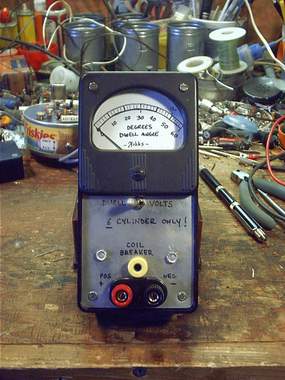
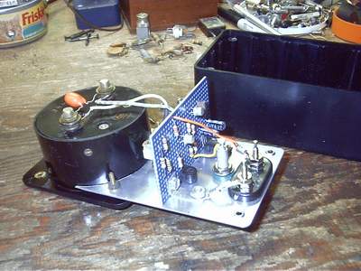
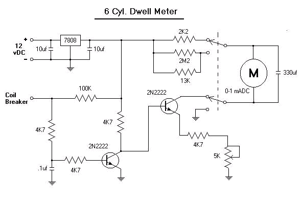
I built this specifically for my Chevy PU so that no one would borrow it. It would be easy enough to add some resistors so it would work with 4 and 8 cylinders (in fact you would just use a 6.8KW resistor instead of a 4.7KW in series with the 5K variable resistor in case you're interested -see schematic below.) But most of my friends don't know this so they won't be borrowing it soon.

The switch has a "Volts" and a "Dwell" position. In the Volts position it measures 0-15 volts DC and I have marked 12 on the meter scale. In the Dwell setting it measures the angle of the dwell by averaging the on-off condition of the coil breaker points.


I used a Simpson 0-1mA meter and turned the face of the dial over, painted it white and drew the proper 0-60 degree scale markings with a Sharpie. To calibrate the meter, simply ground the input and turn the 5KW variable trim-pot until the meter reads 60 degrees. (45 degrees for 8 Cylinder if you're using the 6.8KW series resistor.)

The enclosure is from RadioShack (270-1803) and conveniently enough was the exact size of the Simpson meter. The holes to attach the cover even lined up precisely with studs from the meter. I drilled the studs out to allow screws through to secure the meter. The circuit board is attached to the faceplate with the TO-220 style 7808 voltage regulator and an angle bracket and slides into the slots on the enclosure sides.

My Chev runs pretty well around 32 degrees. I have just completed installing a wiring harness and 3 pin connector to the firewall for quick connect/disconnect.

The circuit is very simple. The 7808 regulator provides a constant DC reference to account for variances in the battery/charging system. The 8 volts is applied through a 4.7KW resistor to the base of the second 2N2222 (Q2) setting it up as a constant current generator for the meter.
The value of the emitter resistor determines the collector current and should be adjusted to read full dwell angle when the coil/breaker lead is shorted to ground. The first 2N2222 (Q1) switches the second to provide it's current source to the meter. When the points of the engine under test are closed, Q1 is off and Q2 passes current through the meter. When the points open, Q1 is forward biased cutting off the flow through Q2 and hence the meter. This takes place much faster than the meter needle can follow, so the meter reading is the average of the two conditions and is the actual dwell angle.

Back to Homebrewed Test Equipment for my shack.

Home to Rock Radio