W0LMD did the real work here,
and to him, I gratefully give credit and thanks. His pages on dishs
and dish feeds
are very useful and helpful. 
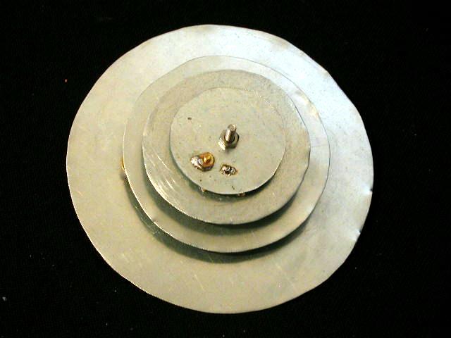
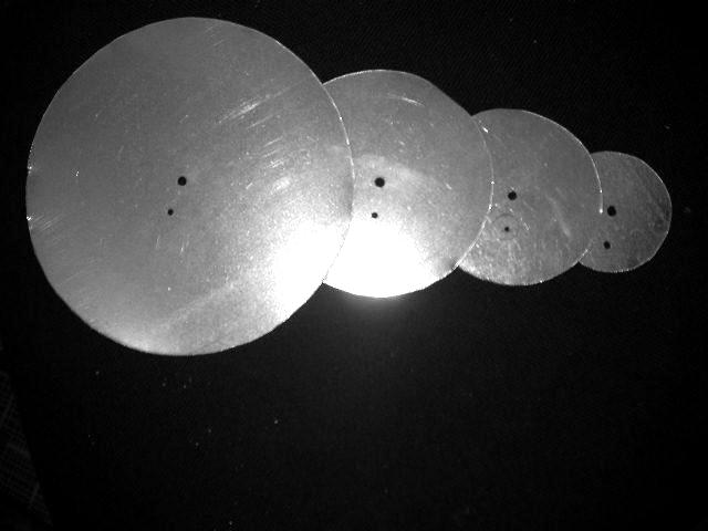
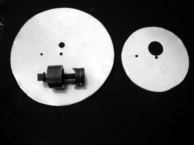
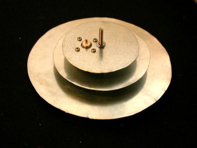
Nonetheless, I found the original instructions difficult to follow, so I wrote up my own pictorial form which may be at least easier to visualize. Let's start with a parts list, that way you can at least know what you need. Then there'll be lots of pictures explaining what to do. Note: Click on pictures on this page to enlarge. |
Parts: 1 - 10"x14" galvanized sheet metal (in roofing department), cut as follows 6 5/8" diameter disk: Rearmost 1269 MHz reflector 4 3/8" diameter disk: 1269 MHz patch 3 1/2" diameter disk: 2401 MHz reflector 2 3/8" diameter disk: 2401 MHz patch 1 - 1 3/4" 10-24 (or 10-32) bolt 3 - 10-24 (or 10-32) nuts 1 - 1/2" steel (or nylon) spacer 2 - 1/4" nylon spacers 1 - 1/2" 6-32 flat head brass bolt 1 - 6-32 brass nut 8 - 1/2" 4-40 flat-head bolts 8 - 4-40 nuts 2 - 1" long 1/4-20 flathead brass bolts 2 - 1/4-20 brass nuts Tools: tin snips or aircraft shears electric drill assorted drill bits up to 3/8" 1/2" countersink (and/or grinder to enlarge holes) 1" Greenlee chassis punch (or hole saw for soft metal) tape measure medium screwdrivers nutdrivers (for 4-40 and 10-32 bolts) soldering iron (not too small) and/or tapping tools file hack saw [optional] compass for drawing circles [optional]
Screw all four disks together with 10-24 bolt and drill 1/8" hole through the remaining three disks using that hole as a guide. |
Unscrew the disks and tap the other 1/8" hole to 6-32 thread (but if
the metal is thin, expect to solder a nut to this point facing away
from the reflectors and don't bother with a tapping tool).
Please see the K5MAN S patch engineering drawing for details if the above instructions aren't clear.
|
Bolt together 1296 MHz patch and reflector, and drill 5/32" hole, 1 5/16" from center and 90° clockwise from 1/8" hole. Drill 1/8" hole out to 3/8" for male N-connector. |
|
I couldn't find the right size of 1/2" spacer, but one size was close enough that it was simply a matter of drilling out the spacer to make the 10-24 bolt fit through it. By using spacers instead of nuts between the patches and their respective reflectors, you can take things apart if something goes wrong later. |
My assembly method differs slightly from the original in terms of the use of spacers. We also start with the 1269 MHz reflector, the largest disk. The 10-24 bolt starts on the connector side and a 1/2" spacer goes on the bolt as shown. 1/2" of #12 copper wire is soldered to the N-connector [not shown here] before the next level is attached. | |
This is followed by the 1269 MHz patch, which is secured by a 10-24 nut as shown. The other end of the #12 jumper is now soldered to the top of this patch (and you won't be able to get to things underneath this patch after that.) | |
We add a 1/4" nylon spacer, secured by a 10-24 nut, and then the 2401 MHz reflector. This is where you find out for sure if need to file down your N-connector to make it fit. | |
We add another a 1/4" nylon spacer, then the 2401 MHz patch, and we secured the
whole thing with a 10-24 nut. Becase we don't use a nut between the 2401
MHz reflector and its patch, we can still take things apart if necessary.
|
Again, we gratefully acknowledge W0LMD, who did the real work here. See some of his other pages on dish feeds and other interesting topics for more project ideas.