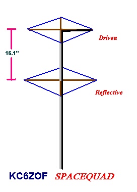
Below is a drawing of my SPACEQUAD design for use in communicating with the MIR Space Station or Space Shuttle (SAREX). The basic idea is so simple, and the theory so obvious that I need not explain it in great detail. It simply consists of a modified 2 meter quad antenna design, pointed to the stars rather than the horizon. It utilizes only a driven and reflective element, eliminating all directors, in order to create a wide parabolic signal, thereby allowing for less pinpoint directivity. Since it faces directly above the fixed location, the directivity must be lessened in order to allow for greater coverage area. The reflector helps eliminate ground noise. This antenna works very well for MIR and SAREX passes that consist of a greater than 50 degree peak elevation (90 degrees is strait up).
The wire loops consist of 12 gauge copper wire which are strung through the 1/4" wooden dowels. 50 Ohm coax of either type RG-58u or RG-8x is used by soldering the center (hot) end to one end of the driven element loop, and the coax shield is soldered to the other end of the driven loop wire, without allowing the driven loop ends to touch each other. The coax is taped to the spreader and draped drown the mast, made of 1" or greater PVC pipe. Either a BNC or PL-259 plug is attached to the radio end of the coax, depending on the type of plug needed for the radio. The mast can be any length, but if very long it should be guyed down with rope to keep it from bending in the wind. The mast can be mounted to anything that will hold it up, on the roof or side of the house; the higher the better. Below are the spacing and element lengths needed.
Reflector loop length = 84.1"
Driven loop length = 82.0"
Reflector spreader loop hole distance = 29.7"
Driven spreader loop hole distance = 29.0"
Spacing between Director and Reflector = 16.1"
Drill 1/4" holes for mounting spreaders, two sets at top and two sets below at 16.1". For each element one spreader will be slightly below the other to allow both dowels to go through the boom. Drill a hole large enough to feed the wire loop through at the distance shown in the table above. Run the reflective element loop through and solder both ends together. Then run the driven element loop wire through the top spreaders and solder one end to the "HOT" coax center, and the other to the "SHIELD" or ground coax wire, and keep these as tight as possible so the loop wire will not slack. Once completed, erect the mast and plug the coax into the radio, and check the SWR before transmitting. If the SWR is High at 148 MHz, and lower at 144 MHz, you will need to shorten the loop length by cutting off about 1/4" at a time; re-soldering and erecting each time. If the SWR is Higher on 144 MHz, you will need to add a little wire. In most case 12 gauge wire will run a 2:1 SWR or less throughout the 2 meter band if everything is cut properly. SWR readings and tuning (cutting/adding) are not necessary if you plan to use the antenna for listening only. HAMs with more experience may wish to employ a short gamma match to the feed point. It does not appear important which way the feed point faces with this quad since polarization for MIR or SAREX is not important.
This quad can also be used to receive data from WO-18 and DO-17 satellites with packet radio equipment. Best of all, whenever the MIR or Shuttle is passing over your location you will hear it clearly, and be able to make a good contact via voice or packet without a lot of power. I have worked the MIR packet station with this quad with only 10 watts output! Hook up your Handy-Talkie and make that QRP contact. As always, if you have any questions, please let me know.