
Slow-Scan Television is a method of picture transmission invented by Amateur Radio Operator Copthorne MacDonald in 1957. Unlike conventional television, Slow-Scan Television permits video images to be transmitted, received, and recorded using inexpensive audio equipment and techniques.
Slow-Scan Television caught my attention while I was a Short-Wave Listener (SWL) in the late 1970s, when I often heard Amateur Radio Operators exchanging Slow-Scan TV signals over the air. Not having the ability to see the images being transmitted literally left me "in the dark". It wasn't long before I began scouring all the books and magazines I could find on the subject, hoping that I might eventually find a way to decode these signals, and literally "see" what was going on.
What I soon discovered is that Slow-Scan TV was nothing like broadcast TV, and that I would need to build a specialized video monitor to view the slow-scan television pictures I was receiving. Considering that I was 14 years old and had no formal training in electronics at the time, this would be a major undertaking. So thrilling were the prospects of eventually being able to see slow-scan television images, that I began making tape recordings of the SSTV signals I was receiving at the time in the hopes I could playback the recordings through my SSTV monitor once its construction was complete.
The recordings I made over 30 years ago served as a valuable resource in testing and aligning my first slow-scan television monitor in 1980. Today, they serve as a fascinating look back in history to a time when picture transmissions took only 8 seconds, were always interspersed with regular voice communications, and shared more in common with standard television hardware than any of the modern approaches to slow-scan television today.
What follows is a brief history and description of some slow-scan television hardware I built and developed over the past 30+ years, along with a look back to my old tape recordings using a recently developed SSTV video scan converter of my own design.
On April 5, 1980, I began constructing an SSTV video monitor patterned after a June 1970 "QST" magazine article entitled, "Slow-Scan TV Viewing Adapter For Oscilloscopes" by Bill Briles, W7ABW, and Robert Gervenack, W7FEN. My exposure to this design came from a re-print of the article I discovered in my father's 1972 edition of the ARRL Radio Amateur's Handbook, as well as the ARRL's Specialized Communications Techniques for the Radio Amateur.
Employing nine transistors, several integrated circuits, and involving external and internal interconnections to an oscilloscope, this was by far the most complex electronic project I had ever undertaken. The circuitry went together in a matter or weeks, although there were a few hard-to-find components and some hardware interface issues that delayed the completion of the project for several months.
On Sunday June 15, 1980, my completed adapter was successfully interfaced to a Heathkit Model O-11 oscilloscope, enabling me to get my first glimpse of Slow-Scan Television at just 15 years of age. The O-11 scope was built by my father in the late 1950s, and actually began life as a less sophisticated Model OM-2 that he later upgraded to an O-11. The scope's 5BP1 CRT, that was part of the original OM-2 design, was replaced with a 5UP7 that possessed the long persistence P7 phosphor needed to retain the SSTV image as it swept down the screen throughout the 8 second transmission period.
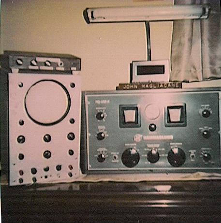
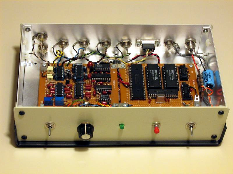
My completed SSTV adapter operated from the top of the oscilloscope in the photo. I constructed the adapter's circuitry on a perforated circuit board, and housed the board in a cardboard cigar box covered in wood grain contact paper. Not pictured are the tape recorder and homebuilt audio console used to route SSTV signals into and out of the recorder while permitting a live display of SSTV signals on the oscilloscope as they were coming in from the receiver.
The adapter's front panel controls adjusted picture contrast, vertical sync threshold sensitivity, and horizontal hold. The horizontal hold control was part of a sync triggered oscillator that I designed into the adapter to reduce line-to-line jitter. The push button to the right of the controls initiated a manual vertical sweep, and the green LED on the far right flashed as video sync pulses were received. This served as a tuning indicator, and was another one of my enhancements to the original design.
Since my communications receiver suffered from frequency drift and mediocre sensitivity, I came up with the idea of designing a high-gain, crystal-controlled converter so that I could receive signals in the 20-meter amateur band by tuning the receiver to a much lower frequency (2.6 MHz) where it exhibited much greater stability. The antenna I used for SSTV reception was a 22 foot long end-fed wire that was strung out of the window.
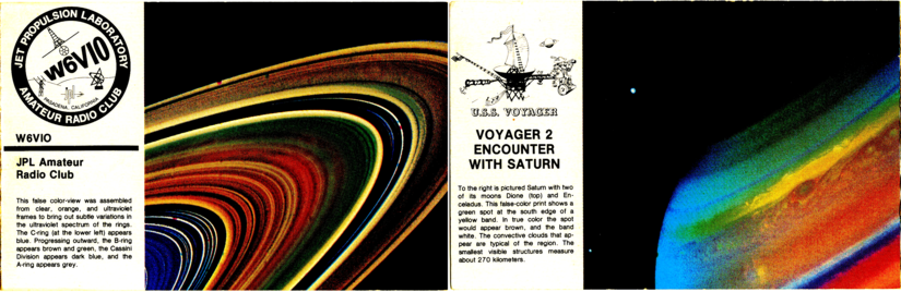
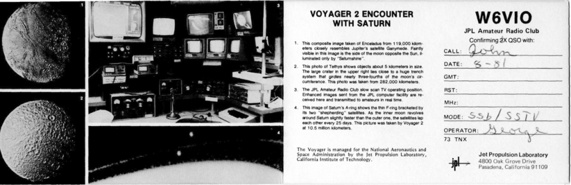
My homebuilt SSTV equipment was used on a regular basis to receive Slow-Scan Television images from across the globe over the period of several years. One of the highlights of this project occurred in August 1981 when W6VIO's Voyager 2 Saturn Commemorative operation employed Slow-Scan Television to televise images of the planet Saturn shortly after their reception from the Voyager 2 spacecraft. Having a front row seat to these never-before-seen images of the planet Saturn, its rings, and its moons was absolutely amazing!
Around the time I began constructing my scope adapter, I purchased a copy of The Complete Handbook of Slow-Scan Television, by Dave Ingram, K4TWJ. This book contained the schematics of several commercial and non-commercial stand-alone slow-scan television monitors. While I had already committed myself to building the scope adapter by this time, a number of the designs published in this book caught my attention. In particular, the Robot Model 70A SSTV monitor appeared to be especially well-engineered.
After using the scope adapter for some time and realizing some of its performance deficiencies, I began gathering parts to build a Robot 70A. Not including the power supply, the circuit for the 70A incorporated 20 bipolar transistors, 9 integrated circuits, and two programmable unijunction transistors, making it at least four times as complex as my oscilloscope adapter.
I began constructing the Robot 70A monitor on February 15, 1981. However, SSTV standards were in flux by the time of its completion, with the emergence of a growing number of color and high resolution monochrome SSTV modes that effectively rendered P7 CRT-based SSTV gear obsolete.
After about a year of study, I became an Amateur Radio Operator in the summer of 1983. I began my Amateur Radio "career" with an Advanced Class license so I could operate on 14.230 MHz, the most popular SSTV operating frequency on the planet. However, contemporary SSTV equipment had grown extremely expensive and prohibitively complex to build by this time, causing slow-scan television to remain a "spectator sport", and my Amateur Radio interests to branch out to other areas for many years.
Despite the obsolescence of 120 line, 8 second frame, monochrome SSTV by the mid-1980s, this video format is one in which I continue to hold a great deal of interest. Through my study of various SSTV equipment designs and product reviews over many years, I became aware of many performance tradeoffs and deficiencies that were inherent in their designs. This led to my realization that the 8 second format had noticeably greater resolution capability than what could be generated or resolved by much of the popular SSTV equipment available during its heyday.
Achieving picture resolution equal in both horizontal and vertical dimensions requires a baseband video bandwidth of at least 1000 Hz, while optimum horizontal sync performance requires a 1200 Hz sync detection bandwidth no greater (or less) than 140 Hz. Few, if any, popular SSTV monitors or scan converters met these criteria.
Released in 1976, the extremely popular Robot Model 400 Scan Converter digitized each video line into just 128 pixels, each having one of only 16 shades of grey. When performing slow-scan to fast-scan conversion, the Robot 400 merely doubled the display of each SSTV line to produce a 256 line FSTV video frame.
While these limitations were imposed for reasons of economy, they had a noticeable impact on picture quality and the overall perception of SSTV's capabilities.
The only commercially available scan converter capable of even approaching the full resolution of the 8-second format was the Videoscan 1000 by Microcraft Corporation (WB9LVI). However, the Videoscan 1000 was a monochrome scan converter that was released in the mid-1980s when the emergence of several color formats compatible with modified Robot 400 scan converters was taking place. As such, the Videoscan never gained a great deal of popularity, leaving few slow-scanners with the ability to experience the true capabilities of first-generation SSTV.
In later years, PCs equipped with popular "Hamcomm" interfaces had their own set of issues in terms of resolution, interference rejection, sync stability, and greyscale linearity. Even some modern day soundcard-based PC SSTV reception techniques fall short in these areas.
Over the years, the thought of designing "The World's Best" SSTV monitor or scan converter capable of operating at slow-scan television's theoretical limits crossed my mind many times. With my old SSTV tapes still in my possession, it seemed like it would be a rewarding endeavor to give first-generation SSTV a second look, and revisit my old recordings using technology far superior than what was available at the time the recordings were made.
During the summer of 2009, I came across a recording I made of the OSCAR-9 satellite transmitting an image of the Earth back in September of 1987. Within a few hours, I managed to build some hardware and write some software that successfully rendered the satellite image on a Linux-based PC. I soon began to think in terms of doing something similar with my old SSTV recordings, and expanding the concept to a stand-alone scan converter with a real-time display.
In January 2010, work on this project began, and I achieved my goal of creating a world-class SSTV scan converter by the Fall of that year.
The scan converter I developed employs a Travis discriminator for SSTV video demodulation, and a 140 Hz wide 1200 Hz bandpass filter to provide sync pulse detection. Demodulated video and sync are processed by a Microchip PIC16F88 microcontroller whose integrated analog to digital converter digitizes the demodulated video at a 4151 Hz rate. Digitized video is then fed to a second microcontroller, a PIC16F77, through a 115.2 kbps serial data link. The 16F77 averages adjacent lines of video, thereby doubling the number of video lines in the image, and providing resolution enhancement and format compatibility with the fast-scan television standard. This microcontroller also keeps track of the SSTV video line and pixel address being processed, and writes each pixel to the appropriate address of a 64 kilobyte array of static RAM, access to which is shared with a third microcontroller, a PIC16F76.
Scan conversion takes place, and fast-scan video is correspondingly generated, as the 16F76 sequentially feeds video data from RAM through a digital to analog converter at a 6 MHz rate. The raw video output of the D-A converter is multiplexed with blanking and sync pulses generated by the 16F76 to form a composite fast-scan video signal.
The overall result of this process is that a slow-scan television image having 128 video lines and an 8.5 second frame rate becomes "line doubled" through pixel averaging, and "sped up" over 1400 times to match the video line and frame rate of a standard NTSC fast-scan television signal, thereby making it compatible with the operation of a standard NTSC television set or video monitor.
Details on the design of my TriplePIC SSTV Video Scan Converter may be found in the Summer and Fall 2014 issues of ATV Quarterly Magazine. My original manuscript for the article may be accessed here in PDF format. Additional information may be found on the TriplePIC website.
The performance of my scan converter has been nothing short of outstanding. Here are a small sampling of SSTV images rendered by my modern-day scan converter that I saw for the first time rolling down the CRT of my old oscilloscope over 30 years ago:
 |
 |
 |
 |
 |
 |
 |
 |
 |
 |
 |
 |
The four level grey-scale at the bottom of each image is representative of video generated by a digital scan converter, such as a Robot 400.
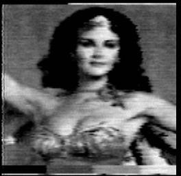
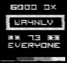
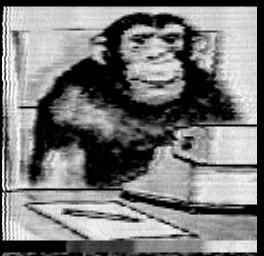
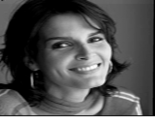
The first row of images were received from Earle, WA4NLV, in Raleigh, North Carolina circa 1979. The first is that of Earle's "upstairs maid" (actress Lynda Carter a.k.a. "Wonder Woman"). Earle used his Apple II computer to generate the graphics in the center image. The gorilla image was used by Earle as a gag to represent a live camera shot of himself sitting behind the computer keyboard during a QSO with WB2BTC (now KC2Q). I've seen Earle use the same image on another occasion to represent a picture of Raleigh's Mayor.
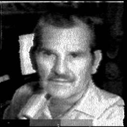
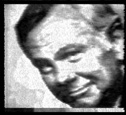
The second row of images were received from Virgil, KG4I, in Birmingham, Alabama on June 14, 1980, while in QSO with Scott, N2BJW, near Elmira, New York. The first image was a live camera shot of Virgil behind the microphone. If memory serves correctly, the source of Virgil's other images was a "TV Guide" magazine. (Incidentally, I contacted Scott last year to share these images with him, and he assured me that he still remembers this QSO, and has a QSL card from Virgil confirming this contact.)
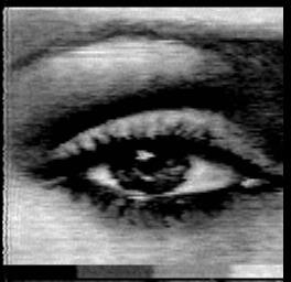
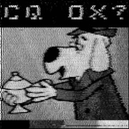
The first two images in the third row are of unknown origin, although I believe the first dates back to 1979. The CQ DX image was transmitted by Ron, WD9ADB of Kokomo, Indiana, with whom I recently had the pleasure of sharing this image.
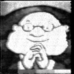
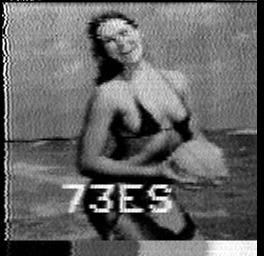
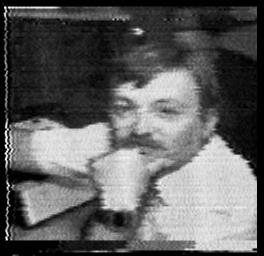
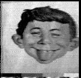
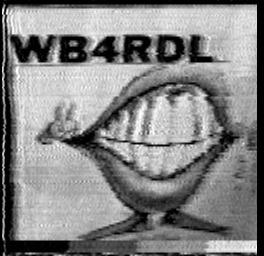
The last row of images were received from Larry, WB4RDL of Rutherfordton, North Carolina beginning with a live mugshot, followed by a picture of Alfred E. Newman, and concluding with a humorous depiction of "Uncle Jimmy's Teeth".
Based on the horizontal jitter in the mugshot, it appears as though Larry might have been getting some RF into his camera. Nevertheless, he appears to be sporting an LED digital wristwatch, and there appears to be an SSTV keyboard (possibly a Robot 800) visible on his desk below his right arm.
In order to illustrate the SSTV reception process in real-time, I developed several Linux-based utilities to merge some of my SSTV audio recordings with the corresponding video demodulated by my scan converter to produce MPEG-4 animations that can be viewed here:
This video was received from KG4I a day before my oscilloscope adapter became operational for the first time. Like so many of my SSTV recordings, this transmission was recorded without the benefit of being able to see what was being received at the time. Initial receiver tuning, and nearly continuous compensation for receiver drift was done completely by ear. (Quite remarkable when I realize I was only 15 years old at the time!)
In this clip, Sam, AC5D, of Stigler, Oklahoma sends 73 at the conclusion of his 20-meter roundtable SSTV QSO. Sam always included some very clever and entertaining drawings in his transmissions. I believe he used a Venus model C1 SSTV camera to make this transmission.
Unlike the Robot 400, I designed my scan converter to have a resolution of 256 pixels per line, with each pixel having one of 255 possible shades of grey, effectively oversampling each line to more than satisfy Nyquist's sampling criteria.
In order to visually assess the resolution capability of my scan converter and that of the 8-second SSTV format itself, I needed a source of SSTV video having far better quality than any of my old recordings. I used some Linux-based software I wrote several years prior to generate 8-second, 128-line monochrome SSTV signals through my PC's soundcard. The scan converter was connected to the output of the soundcard, and the video demodulated by the scan converter was fed back to the PC using the scan converter's high-speed serial interface. Another piece of software was created to display the video as it was being demodulated by the scan converter and fed back to the PC, snapshots of which were captured using GIMP v2.6 software for final evaluation.
The results of this assessment were absolutely amazing as the captured images below clearly illustrate.
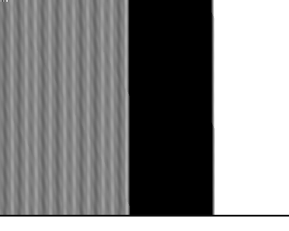
As a "sanity check", I included a third column to illustrate the performance of popular MMSSTV v1.13A software using the Hilbert Transform demodulator option. MMSSTV was run under Linux using Wine, with SSTV signals imported to MMSSTV using .wav audio files having an MMSSTV-compatible 11025 Hz sampling rate. Images demodulated by MMSSTV were saved as .bmp files rather than .jpg, and converted to .png format so as not to incur any resolution loss. Note that MMSSTV treats 8-second SSTV video as having a 4:3 aspect ratio rather than the 1:1 ratio specified in the original SSTV standard, causing the images to be stretched horizontally by 33%.
 |
 |
 |
 |
 |
 |
 |
 |
 |
 |
 |
 |
|
|
|
The images in the first and second rows were originally in a 128 pixel/line by 128 line format, and were transmitted as such in a standard 128-line SSTV format. Since my scan converter samples each video line 256 times, and since my image display software averages adjacent video lines to simulate the process my scan converter uses to produce 256 line NTSC video, the size of the original images were doubled in each dimension to affect an equal comparison.
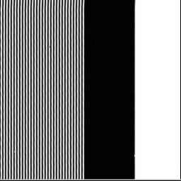
The resolution chart in the first image was created during the design and testing phase of my scan converter. The converter's video discriminator was designed to possess an equal response between the 128 pixel/line high frequency video on the left-hand side of the image and the low frequency video on the right. As can be seen, video response is flat between these two extremes. MMSSTV doesn't come anywhere close to resolving that level of detail.
The final test image was originally in a 256 pixel/line by 256 line format, and was sent as a 128 line image by transmitting only the even numbered lines in the original image. The odd lines were reconstructed in my scan conversion and SSTV display process by averaging the adjacent video lines that were transmitted. By comparison, MMSSTV appears to merely double each video line, yielding much poorer vertical resolution. Close inspection of this image reveals some non-linearity in MMSSTV's greyscale rendition as well.
Slow-Scan Television continues to evolve as more sophisticated methods of narrowband picture transmission and reception are developed and deployed by Radio Amateurs throughout the world. As a result of this technological progress, today's Slow-Scan Television bears little resemblance to what was in vogue when my exposure to SSTV first occurred in 1980. However, SSTV's original picture format and transmission standards, long given up for dead, give a surprisingly good account for themselves when modern signal processing techniques are employed, making them worthy of a second look.

|
John Magliacane Amateur Radio Operator: KD2BD |