
SPLAT! is an RF Signal Propagation, Loss, And Terrain analysis tool for the electromagnetic spectrum between 20 MHz and 20 GHz.
Applications of SPLAT! include site engineering, wireless network design, amateur radio communications, frequency coordination, communication system design, and terrestrial analog and digital television and radio broadcasting.
SPLAT! provides site engineering data such as the great circle distances and bearings between sites, antenna elevation angles (uptilt), depression angles (downtilt), antenna height above mean sea level, antenna height above average terrain, bearings and distances to known obstructions based on U.S. Geological Survey and Space Shuttle Radar Topography Mission elevation data, path loss and field strength based on the Longley-Rice Irregular Terrain as well as the new Irregular Terrain With Obstructions (ITWOM v3.0) model, and minimum antenna height requirements needed to establish line-of-sight communication paths and Fresnel Zone clearances absent of obstructions due to terrain.
SPLAT! produces reports, graphs, and highly detailed and carefully annotated topographic maps depicting line-of-sight paths, path loss, field strength, and expected coverage areas of transmitters and repeater systems. When performing line-of-sight analysis in situations where multiple transmitter or repeater sites are employed, SPLAT! determines individual and mutual areas of coverage within the network specified. SPLAT! also produces .geo Georeference Information Files for interoperability with Xastir software, and .kml Keyhole Markup Language files for interoperability with Google Earth.
SPLAT! is free software. It may be redistributed and/or modified under the terms of the GNU General Public License Version 2 as published by the Free Software Foundation.
Download SPLAT! source code and associated data files for your area through the following links:

| 
| 
| 
|
Latitude and Longitude information may be determined from a specific street address through www.locates.com.au. For areas within the United States, sites such as the US Census Geocoder may be used.
Note that SPLAT! uses coordinates based on WGS-84 or NAD83 datum. Older NAD27 coordinates can be converted to NAD83 coordinates using an on-line conversion utility. The gdal_translate utility included in the GDAL - Geospacial Data Abstraction Library is useful for converting topography data in GeoTIFF format to SRTM .hgt files that are compatible with SPLAT!'s strm2sdf utilities. An excellent command-line utility capable of converting the Portable PixMap (PPM) topographic map files generated by SPLAT! into highly compressed Portable Network Graphics (PNG) files is OptiPNG. OptiPNG may be downloaded from the OptiPNG Home Page.SPLAT! is invoked via the command-line, thereby permitting batch operations, or even background processing with user-defined priorities that can be performed either locally, or via remote workstations. Generated topographic maps are in the form of 24-bit (True Color) Portable Pixmap (PPM) image files that can be easily viewed and/or converted to other formats using standard Unix applications and utilities. Through gnuplot, SPLAT! generates terrain profile plots in GIF, PNG, Postscript, Adobe Illustrator, AutoCAD dxf, LaTeX, and many other formats supported by gnuplot. SPLAT! also generates obstruction and path-loss reports in the form of plain ASCII text.
The following are several examples of some of the data generated by SPLAT! Software:
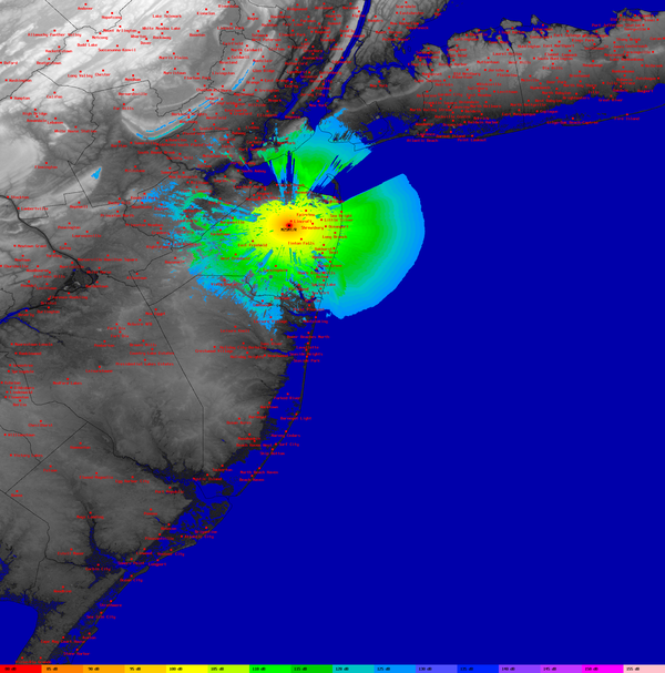
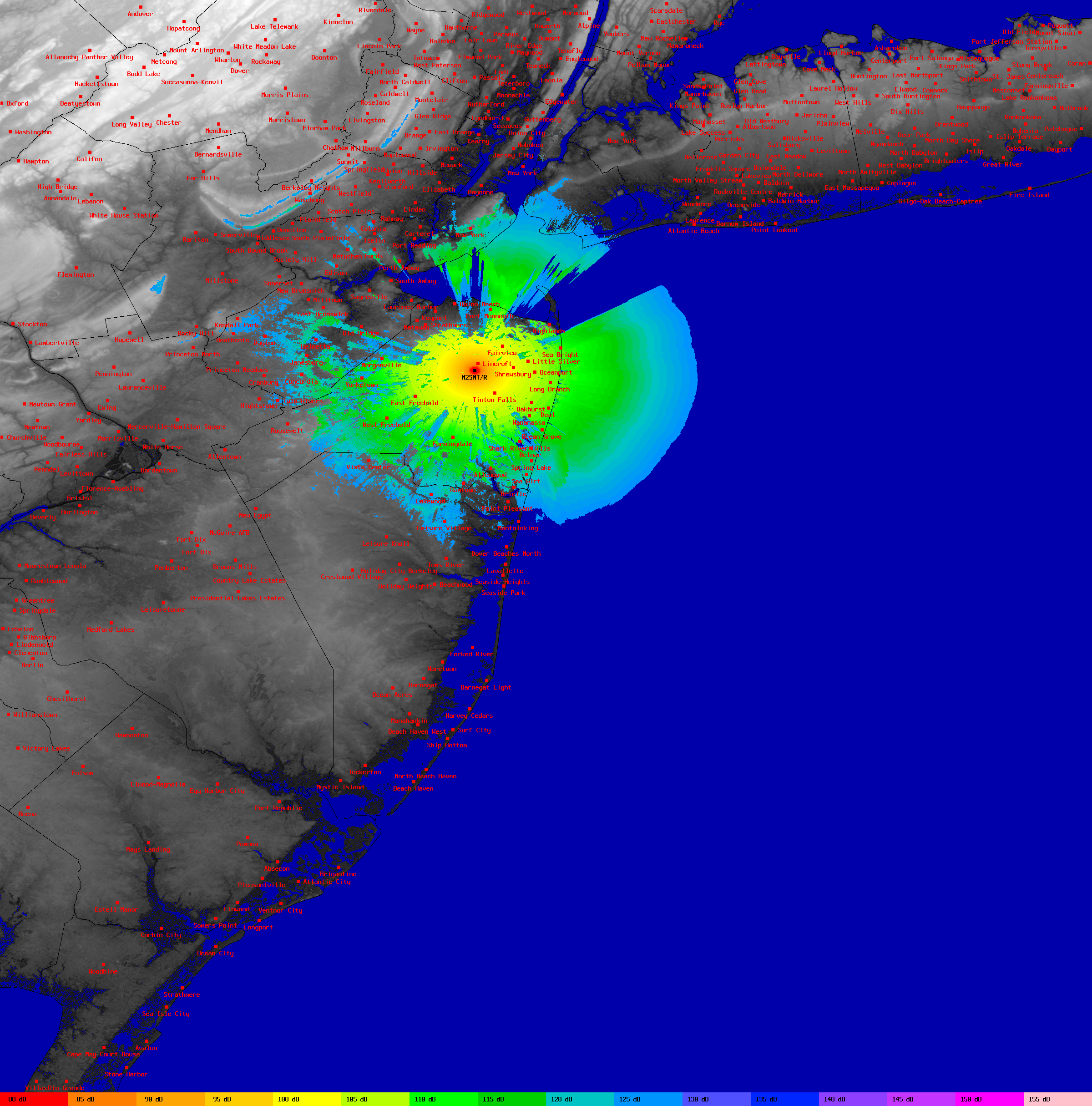
Figure 1 is a thumbnail representation of a much higher resolution (2400x2430 pixel) repeater coverage map generated by SPLAT! software. Each color represents a discrete level of path loss based on the Longley-Rice irregular terrain propagation model, assuming a frequency of 439.250 MHz, horizontal polarization, and a receiver antenna height of 30 feet above ground level.
A legend at the bottom of the figure maps each color to a specific level of signal attenuation in dB. Effective coverage can be determined knowing the transmitter ERP, receiver noise figure, receiver antenna gain, frequency, bandwidth, and the minimum signal-to-noise ratio requirements.
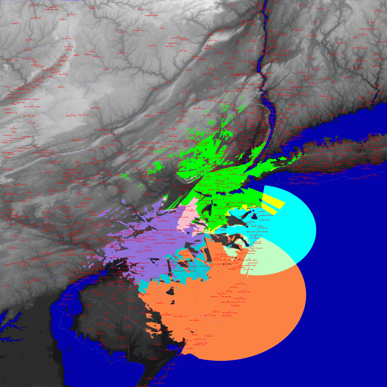
In Figure 2, SPLAT! displays the line-of-sight coverage areas of four UHF-FM repeaters that are part of the W2NJR linked repeater system in New Jersey. Individual as well as mutual areas of coverage are clearly visible in this thumbnail image. Full resolution of this image is 3600x3600 pixels.
Figure 3 shows the line-of-sight paths between two transmitter sites and a common receiver site. In this example, the receiver is located 20 feet AGL in Oyster Bay, NY. The line-of-sight path between the Empire State Building and Oyster Bay is displayed in cyan, while the path between the Armstrong Tower in Alpine, NJ and Oyster Bay is displayed in green.
Line-of-sight conditions are absent for either path. An antenna at least 95 feet AGL is required to reach the Armstrong Tower. At least 82 feet of altitude is required to reach the Empire State Building over a line-of-sight path.
Figure 4 illustrates a point-to-point path profile generated by SPLAT! Version 1.2.0. In this example, normalized terrain heights referenced to the line-of-sight path between two tower sites are plotted as a function of distance from the receive site on the left. This plot shows a line-of-site path unobstructed by terrain clearly exists between the Lincroft and Lawrence Township sites. In addition, clearance of the first Fresnel zone is demonstrated. The Earth's curvature contour against which the terrain has been plotted is displayed at the base of the plot.
WFUT-TV 68's directional contour is illustrated in Figure 5 using SPLAT! Version 1.2.0. Although transmitting from New York City, WFUT's signal is directed west northwest toward Newark, New Jersey, the station's actual city of license.
Beginning with version 1.2.0, SPLAT! can generate KML files compatible with Google Earth when performing point-to-point analyses:
Google Earth's navigation tools allow the user to identify landmarks, roads, and other featured content.
In addition to graphic output, SPLAT! also produces data in the form of plain text. The following are a sample of some of the reports generated by SPLAT! software:
		--==[ SPLAT! HD v1.4.0 Path Analysis ]==--

---------------------------------------------------------------------------

Transmitter site: WNYE-DT 25
Site location: 40.7561 North / 73.9867 West (40° 45' 21" N / 73° 59' 11" W)
Ground elevation: 45.93 feet AMSL
Antenna height: 1013.78 feet AGL / 1059.71 feet AMSL
Distance to Oyster Bay: 25.26 miles
Azimuth to Oyster Bay: 72.14 degrees
Depression angle to Oyster Bay: -0.5709 degrees
Depression angle to the first obstruction: -0.5694 degrees

---------------------------------------------------------------------------

Receiver site: Oyster Bay
Site location: 40.8673 North / 73.5265 West (40° 52' 2" N / 73° 31' 35" W)
Ground elevation: 131.23 feet AMSL
Antenna height: 25.00 feet AGL / 156.23 feet AMSL
Distance to WNYE-DT 25: 25.26 miles
Azimuth to WNYE-DT 25: 252.44 degrees
Elevation angle to WNYE-DT 25: +0.2053 degrees
Elevation angle to the first obstruction: +0.6256 degrees

---------------------------------------------------------------------------

ITWOM Version 3.0 Parameters Used In This Analysis:

Earth's Dielectric Constant: 15.000
Earth's Conductivity: 0.005 Siemens/meter
Atmospheric Bending Constant (N-units): 301.000 ppm
Frequency: 533.000 MHz
Radio Climate: 5 (Continental Temperate)
Polarization: 0 (Horizontal)
Fraction of Situations: 50.0%
Fraction of Time: 90.0%
Transmitter ERP: 200.000 kilowatts (+83.01 dBm)
Transmitter EIRP: 327.363 kilowatts (+85.15 dBm)

---------------------------------------------------------------------------

Summary For The Link Between WNYE-DT 25 and Oyster Bay:

WNYE-DT 25 antenna pattern towards Oyster Bay: 0.745 (-2.55 dB)
Free space path loss: 119.18 dB
ITWOM Version 3.0 path loss: 150.30 dB
Attenuation due to terrain shielding: 31.12 dB
Total path loss including WNYE-DT 25 antenna pattern: 153.02 dB
Field strength at Oyster Bay: 63.92 dBuV/meter
Signal power level at Oyster Bay: -67.87 dBm
Signal power density at Oyster Bay: -81.86 dBW per square meter
Voltage across a 50 ohm dipole at Oyster Bay: 115.56 uV (41.26 dBuV)
Voltage across a 75 ohm dipole at Oyster Bay: 141.53 uV (43.02 dBuV)
Mode of propagation: 2_Hrzn_Diff
ITWOM error number: 0 (No error)

---------------------------------------------------------------------------

Between Oyster Bay and WNYE-DT 25, SPLAT! HD detected obstructions at:

    40.8653 N,  73.5352 W,  0.48 miles, 183.73 feet AMSL
    40.8652 N,  73.5355 W,  0.49 miles, 196.85 feet AMSL
    40.8651 N,  73.5361 W,  0.52 miles, 200.13 feet AMSL
    40.8648 N,  73.5371 W,  0.58 miles, 203.41 feet AMSL
    40.8618 N,  73.5496 W,  1.26 miles, 216.54 feet AMSL
    40.8618 N,  73.5498 W,  1.28 miles, 232.94 feet AMSL
    40.8617 N,  73.5501 W,  1.29 miles, 236.22 feet AMSL
    40.8616 N,  73.5504 W,  1.31 miles, 239.50 feet AMSL
    40.8615 N,  73.5509 W,  1.34 miles, 246.06 feet AMSL
    40.8614 N,  73.5512 W,  1.35 miles, 249.34 feet AMSL

Antenna at Oyster Bay must be raised to at least 96.00 feet AGL
to clear all obstructions detected by SPLAT! HD.

Antenna at Oyster Bay must be raised to at least 227.00 feet AGL
to clear the first Fresnel zone.

Antenna at Oyster Bay must be raised to at least 170.00 feet AGL
to clear 60% of the first Fresnel zone.
|
--==[ SPLAT! HD v1.4.0 Site Analysis Report For: WNJT-DT ]==-- --------------------------------------------------------------------------- Site location: 40.2827 North / 74.6864 West (40° 16' 57" N / 74° 41' 11" W) Ground elevation: 88.58 feet AMSL Antenna height: 990.00 feet AGL / 1078.58 feet AMSL Antenna height above average terrain: 952.75 feet Average terrain at 0 degrees azimuth: 159.45 feet AMSL Average terrain at 45 degrees azimuth: 102.03 feet AMSL Average terrain at 90 degrees azimuth: 103.53 feet AMSL Average terrain at 135 degrees azimuth: 112.20 feet AMSL Average terrain at 180 degrees azimuth: 82.33 feet AMSL Average terrain at 225 degrees azimuth: 71.10 feet AMSL Average terrain at 270 degrees azimuth: 158.90 feet AMSL Average terrain at 315 degrees azimuth: 217.11 feet AMSL --------------------------------------------------------------------------- |


No animals were harmed, nor any Micro$oft products used in the creation or distribution of this page.
SPLAT! software is Copyright
© 1997-2025 by John Magliacane,
KD2BD.
For information on other software developed by this author, please
see the software page.