Measured Performance Of The WB0QCD Alford-Slot Antenna


You've seen the ads. "5.6dBd gain...flat VSWR and good gain bandwidth performance over the entire 420-440 MHz band..." But just how well does the WB0QCD antenna perform in real life? We put ours to the test on a professional antenna range, and the results we found were less than impressive!
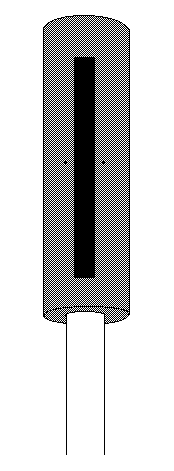
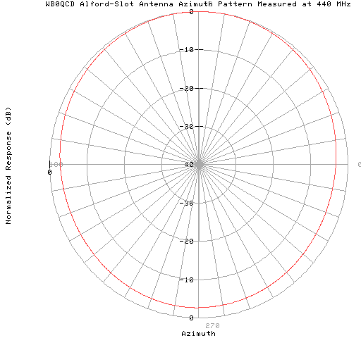
First, the good news. The WB0QCD Alford-Slot antenna is a mechanically solid antenna that does exhibit a horizontally polarized, omni-directional radiation pattern. The E-plane pattern is consistant with that of a single axially slotted cylindrical antenna with a small diameter/wavelength ratio (see G. Sinclair, "Patterns of Slotted-Cylinder Antennas", Proceedings of the IRE, vol. 36, pp.1487-1492; December, 1948). The antenna is about 3 dB more responsive in the direction of the slot than it is off the rear of the antenna. This feature is consistant across the entire 420 MHz to 450 MHz band.

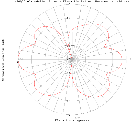
Now for the bad news. The elevation pattern of the WB0QCD Alford-Slot antenna is very poor. The pattern is multi-lobed, and as the frequency is increased, the pattern gets worse. At 426 MHz, the WB0QCD Alford-Slot antenna exhibits the following radiation pattern:

Although the pattern is multi-lobed, the major lobes are directed toward the horizon where they will do the most good. Still, quite a lot of energy is lost at angles where it does no good. Gain calculations based on this pattern data indicates that the WB0QCD Alford-Slot antenna averages approximately 3.64 dB gain over an isotropic source at 426 MHz. That's just 1.5 dB better than a dipole, and 4 dB below advertised claims!
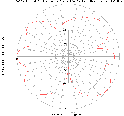
As the frequency is increased, the situation becomes worse. At 439 MHz, the pattern is so disturbed that the lobe at the horizon becomes the minor lobe, and the majority of the antenna's response is lost at useless elevation angles, approximately 45 degrees above and below the horizon.

Gain calculations based on this pattern data indicates that the WB0QCD Alford-Slot antenna averages less than 1.9 dB gain over an isotropic source at 439 MHz. That's less gain than that of a dipole!
Our WB0QCD Alford-Slot antenna was also tested for VSWR between 420 MHz and 440 MHz. The lowest VSWR measured throughout this spectrum was 2:1. A quarter-wave coaxial transformer was installed at the antenna's feedpoint to provide a better match to the 50 ohm transmission line.
The poor performance of the WB0QCD Alford-Slot antenna appears to be rooted in the fact that the radiating slot is simply too long. Antennas, by John Kraus (W8JK) reports that for resonance, the length of a slot cut into a cylinder must be longer than a half-wavelength. Specifically, a half-wavelength slot must measure 0.75 wavelengths. The WB0QCD Alford-Slot measures two wavelengths in length, producing an antenna with the radiation pattern equivalent to that of a 1.5-wavelength dipole. At this length, the slot radiates a multi-lobed pattern that is poor for any type of communication.
The reference by Kraus also confirms that "Rib Cage Slot" antennas are simply approximations to solid cylinders, and produce radiation patterns similar to those of Alford-Slot antennas of identical length.
Pattern data doesn't lie. Although well constructed, the WB0QCD Alford-Slot Antenna (and relatives) fall far short of their advertised performance claims in terms of gain and operating bandwidth because of their improper design.
|
|
John Magliacane |