My Elecraft K2/100 S/N 3563 transceiver was built in June 2003 and placed on the air shortly thereafter. Several modifications were made to the SSB adapter board to improve the transceiver's performance on single sideband. These included KI6WX's increased gain and crystal filter bandwidth modifications as well as a few of my own. The following discussion describes the measured performance of my transceiver after these modifications were completed.
Even after modifying the SSB filter bandwidth of my transceiver from the original 2.0 kHz to 2.5 kHz, I remained somewhat dismayed by the quality of my on-air audio on lower sideband. Using a Grundig YB-400 receiver (10 kHz wide bandwidth) as a monitor, no CAL FIL setting seemed appropriate to equalize the audio bandwidth, frequency response, and audio quality on both USB and LSB. USB sounded great, while LSB sounded either muffled or tinny, to my ears at least, with no happy medium. The difference between LSB and USB seemed less pronounced on receive.
Tests with various microphones revealed that if the low-end audio response were rolled off and CAL FIL re-adjusted, better equalization could be obtained between USB and LSB transmitted audio response. In an effort to roll off the low-end, audio coupling capacitor C32 (0.1uF) was reduced to 0.0056uF (ideally 0.0033uF for a 300 Hz cutoff), while C31 (2.2uF) was replaced by a 0.47uF capacitor. After this change, things started sounding better. As an added bonus, the speech compressor and balanced modulator are now less likely going to be driven by audio frequencies that have little or no chance of making it through the sideband filter.
Still curious about the actual audio response of the transceiver on single sideband, I wrote a small computer program under Linux to sweep across the audio spectrum and measure the amplitude of the audio returned through the soundcard. I also built a very simple crystal controlled direct-conversion receiver that included no AGC or filtering of any kind for accurate on-air signal monitoring. The K2 was driven well below the point of ALC action. The data obtained by the sweep was plotted using gnuplot. The results answered some questions, but raised several others in the process.
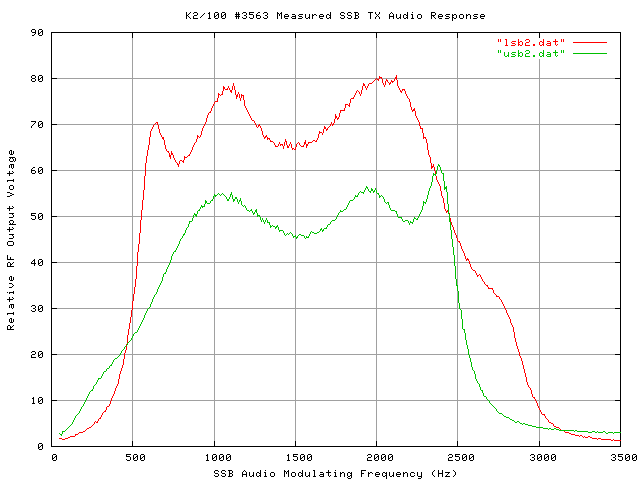
Figure 1 displays the results of injecting audio directly into Pin 1 of the balanced modulator chip. This effectively bypassed the speech compressor and the audio response characteristics resulting from the series coupling capacitors in the speech amplifier chain.
Ripple in the passband of the SSB crystal filter can easily be seen in this linear plot, but only amounts to about 1.5 dB peak-to-peak, which is quite respectable. Each response is fairly well centered, considering the matching through CAL FIL was done entirely through aural methods. Surprisingly, USB output was found to be 3 dB below that of LSB! Perhaps this is indicative of the balanced modulator receiving less carrier injection from the VXO-controlled carrier oscillator in LSB mode. If this is indeed the case, perhaps it also explains why the precise point of carrier balance is inconsistent between LSB and USB. At any rate, the discrepancy in output level is undoubtedly compensated through ALC action in the transmitter when the K2 is operating under normal operating conditions and power levels.
Close inspection of this plot also reveals a slight roll off at lower audio frequencies. Perhaps this is due to the effects of C23 (0.33 uF), which supplies an AC ground to the balanced modulator audio input. With a modulator input impedance of 1500 ohms, the value chosen for C23 would result in a 3 dB cutoff of about 300 Hz, which appears consistent with the measured data. More important, however, is the slope of the SSB filter on each side of the passband. On LSB, the low-end cutoff is very sharp, while the high-end cutoff is less abrupt. The absence of a gradual roll off on the low-end can certainly explain the critical nature of CAL FIL adjustments experienced in LSB mode. On USB, the sharp cutoff is on the high-end where less audio energy is present, making its exact placement in the audio spectrum less critical.
The 3 dB bandwidth of the SSB filter was found to be only slightly over 2 kHz, leaving one to wonder what the bandwidth was prior to the crystal filter bandwidth modification.
Next, audio was injected into the microphone connector of the transceiver. The result is a complete, overall picture of the K2's transmitter audio response.
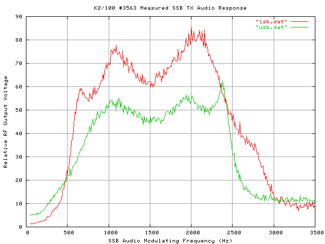
In Figure 2, the effects of the low frequency audio roll-off modifications can be seen, and are most pronounced on the LSB curve, which is the desired result. In particular, the sharp peak on the low frequency end of the response curve is reduced about 1.3 dB, effectively melting it into a broad slope that terminates at the second peak in the filter's response, just above 1000 Hz. Unfortunately, this roll off reduces the already narrow audio bandwidth of the transmitter still further, bringing it under 2 kHz.
Note that the curves made during the second sweep are a bit noisy. The noise is believed to be the result of the speech compressor or related circuitry. Under normal operating conditions, this noise is negligible.
In this test, the transceiver's VFO was swept across the K2's 4 MHz internal "birdie", and the resultant audio from the headphone jack measured through the soundcard. The K2's RS-232 interface was used to sweep the receiver across the frequency range needed for this test.
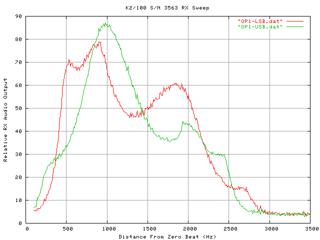
Figure 3 reveals not only the response of the KSB2's sideband filter, but also the effects of receiver's post-IF amplifier filter in concert with the response of the receiver's audio amplifier.
Response is highest at or below 1000 Hz, and this is probably the result of low-pass filtering in the receiver's audio amplifier. Note: CAL FIL was adjusted slightly on the LSB filter between the times the TX and RX sweeps were performed, and the position of the peaks in the LSB curves illustrate this.
With so much "tilt" in the response, it is difficult to accurately measure the 3-dB bandwidth, except perhaps by identifying the 3-dB cutoff on the low frequency side of one curve, and using symmetry to identify the corresponding point on the high frequency side of the other filter's plot.
The shape of the K2's SSB TX frequency response, including the number of peaks and valleys in the audio passband, were found to be entirely consistent with a properly functioning ladder filter. The bandwidth was discovered to be narrower than expected, making the exact placement of the carrier oscillator (through CAL FIL) somewhat critical, especially on lower sideband. Due to the K2's frequency mixing scheme, the lower sideband I.F. filter response is the one normally employed during regular SSB operations on the 160, 80, 40, 15, 12, and 10 meter bands. Microphones designed for communication service (those with response peaks around 3000 Hz) may produce disappointing results due to the narrow bandwidth of the K2's sideband filter.
Lastly, while all results depicted here appear to be reasonable and accurate, it should be emphasized that due to variations in the crystals used in the SSB filter, the results and conclusions provided here may not necessarily apply to all K2s.


No animals were harmed, nor any Micro$oft products used in the creation or distribution of this page.

|
John Magliacane Amateur Radio Operator: KD2BD |