

The J-Pole antenna is an antenna design that has been around for many years. While I am basically regurgitating information here, I'm adding my own "spice" to the flavor. Basically, it means that I'm adding my own insight obtained through trial and error... and success! First of all, I'm not going to bore you with basic construction notes. There are plenty of others that have gone to great lengths to develop the basics of the construction of this fine antenna, you can find some of them here:
And that's basically it. Plenty of other sites out there with J-Pole information, but I have found much success with these designs.
This is what you'll need if you want to build your own:
So, why is it called a J-Pole?
Well, because it's shaped like a J! While there are J-Pole antenna designs that utilize copper piping, they are meant for outdoor use. That is not within the scope of this article, so you can find them elsewhere. When all is said and done, the copper wire resembles the shape of a 'J', with the exception of the Slim-Jim, as it resembles more of a C. So, maybe that should be called the C-Pole? It just doesn't have the same ring to it...
Well that's all good and fine, but why build a J-Pole?
I build my J-Poles because it's a challenge. You get your ticket, you get your radio and suddenly you want to be able to talk on it further than with that short, stubby rubber duck antenna. Maybe you're stuck living in an apartment, preferably on the top floor, and the landlord won't let you put antennas up outside, or it's simply too impractical to erect outdoor antennas. Maybe the same is true in your house, perhaps you live within a Home-Owners Association (HOA) and the neighbors think that antennas are unsightly. Putting up a J-Pole antenna in your attic, of all places, could still get you on the air. Maybe you live in a place where the weather can become treacherous, such as next to a lake, ocean or Tornado Alley. Knowing that you've got a stable means of communicating without worrying if the outdoor antenna is going to come crashing down can save not only your sanity, but your pocketbook as well.
So why did I switch from twinlead over to ladderline?
Twinlead is plentiful, but Ladder-Line puts a bit more space between the two copper wire elements that run in parallel. This makes working with Ladder-Line easier and results in a more efficient antenna. The other nice thing is that it's possible to make J-Poles for bands other than 2 meters with Ladder-Line much easier than with Twin-Lead. Even on some HF, Ladder-Line works great, such as on 6-meters and 10-meters. Some G5RV antennas are fed with Ladder-Line and a matching Balun, thus making it the perfect material for passing any sort of Radio Frequency across.
Wait, did you say 6-meters AND 10-meters?
You betcha! Numerous designs exist, but when you want to get down to the meat of it all, it's easier to plug your numbers in and get the desired result. Special thanks to KK1CW for making this possible. Of course, you will run into some constraits at these frequencies, so you'll need to develop a solution of your own to work. I am always open to new methods to make it work, so if you find any of this helpful and would like to share your ideas, please feel free to let me know.
So... got any pictures?
Sure do, here they are. For finer detail, click on a picture:
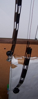
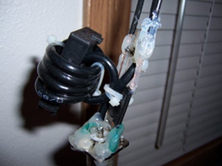
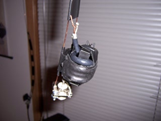
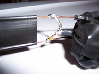
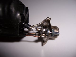
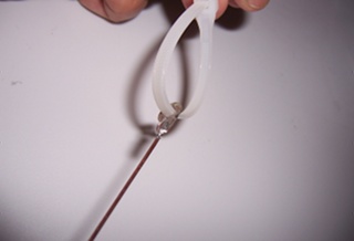
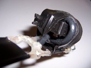
Talking on local repeaters, I attain "full quieting" at 5 or 10 watts using the 5/8 wave antenna. On a good day, further repeaters may be met, but on most days the 1/2 wave antenna will get there. What good would a 1/4 wave J-Pole do? Only the future can answer that... 73's!