1929 Hartley Transmitter
After I built the 2-tube regenerative receiver (elsewhere in this site) I thought it would be fun to build a complete station similar to what a typical ham would have operated in the late 1920's. A historical chain of events occured in the early to mid '20s that is of great importance today. First of which is the "Shortwave Era", when Amateurs began operating on the HF frequencies. Also, the vacuum tube replaced the spark gap transmitter that was previously used. I chose to build a transmitter that was state of the art during that time. This transmitter is monoband and operates on the 80 meter band, from 3.5MHz - 3.7 MHz. It puts out a reasonably clean signal, but it does have its own unique sound. Every transmitter built will have different characteristics, and no two will sound alike.
Well, here is how to build your own 1929 Hartley transmitter.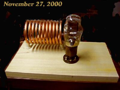
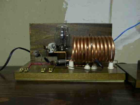
I began first by rounding up all my old parts I had. Also cut the wood (I used Poplar) thatI was going to use for the base. My piece of wood is about 12 inches by about 8 inches. I didn't stain or varnish it until I knew I hada working circuit. It's easier to sand off solder burns than it is to remove them from a varnished board. I have about 3 or 4 oldtime tube sockets made in that era, and were meant to be mounted on a wooden base, so I used one of those for the tube. Although I wished I hada #45 triode, I did find a #10Y in the junkbox and I decided to use that. (I am still looking for a #45, a store near me may have some in their attic). I wound the coil, using 1/4 inch copper water pipe, and I used a standard spray paint can as a temporary coil form. I wound 11 turns around it, and carefully slid the can out of the coil, flattened the ends and mounted it to 2 standoff insulators I had in the junquebox. The above picture is what the transmitter looks like after I completed step 1.
The next step was to make the 1-turn link.
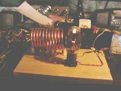
That was mounted in the center of the main coil, and is about 1 inch larger in diameter than the big copper coil. That link is mounted using another pair of smaller standoff insulators in the center of the main coil.I then wired the filament connections to a pair of fahnstock clips mounted on the rear of the board. The #10 filaments are rated for 7.5 volts, but I use a 6 volt transformer, and I get plenty of emission with the reduced voltage. Of course, I HAD to take a quick picture of the lit tube, pardon the messy bench. hi. NoticeI used modern plastic covered wire to make the connections. This is the only place in the transmitter that uses insulated wire, and if you wanna make it look even more origional, use double cloth covered wire like they used back then. Trouble is, its not made anymore that I know of, so good luck in finding some.
Here is the picture of the transmitter when all the wiring is finished. This is how it looked when it made its first contact with a ham across town in Hubbard, OH. Jerry, W8JV was my first contact using this transmitter. Jerry is an old time radio afficianado, so I felt that he would be the logical choice to arrange a schedule with. All of the wiring is point to point, using #12 solid bare copper wire. This is done not only for looks, but all of the wiring needs to be "stiff" to prevent frequency instability. Since this is a VFO coupled directly to an antenna, any physical changes, vibration and wire movement, antenna movement etc will cause small frequency changes. This is also the reason for the copper tubing coil, but also because there is very high RF current running thru the coil. The tuned circuit has a very high Q, you need at least 400pf to resonate the coil on 80 meters. Since air capacitors ofthat size are difficult to find, you can use a bank of silver-mica capacitors. Select fairly small values at fairly high voltage ratings. 8 - 50pfat 1000 volt units can be paralleled with a 100 pf variable. This should give you decent frequency control. You will need to experiment a little with the exact capacitance you will need to make it tune the bottom of 80.
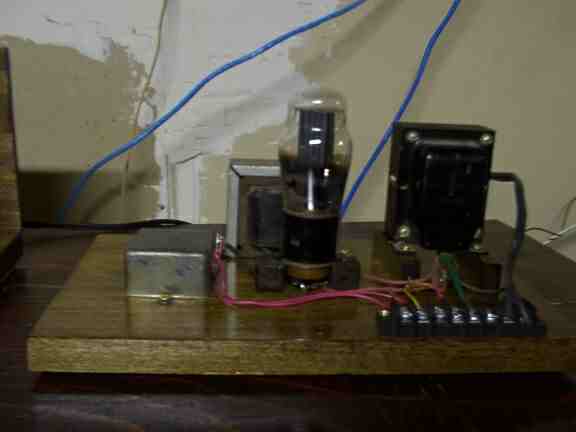
Here is the power supply.
There isnt anything special about it. All you need for this piece is a power transformer
that outputs about 500VCT, 6.3 VAC and 5VAC. I used a #80 rectifier tube. If you want this
to power the receiver, you will have to use a zener diode to regulate to 45 volts.
I dont see any way around using a semiconductor device to do it.
Only a few milliamps are needed, so a 5 watt diode is probably overkill, but its safe.
You can set it to regulate up to about 50 milliamps or so. A resistive divider wont cut it.
The current draw varies whether the detector is oscillating or not,
and it will make the regeneration control very difficult to adjust to the threshold.
(I hid a zener under the power transformer). It just looks like a couple extra wires coming off it. When finished, this supply will deliver 250 -300 volts DC under load for the
plate supply, and 6.3 volts AC for the filaments. DC hum is low enough to be
inaudible. Remember to use 450 volt capacitors for the supply filter.
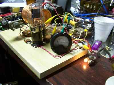
This is the finished transmitter after it was rebuilt on stained wood and
tuning caps and such are mounted. I did not mount the milliammeter on the
front of the transmitter as yet as I only have 1 suitable meter and didnt want
to install it quite yet as I am contemplating another similar project. A
meter can be mounted on the front panel of either the transmitter or on the
power supply. Just wire it in series with the negative or positive lead. On
this transmitter, it can be tied between the power supply and transmitter as
it is only one stage. Rebuilding this was very easy, as with all ofthe stiff wiring, you only need
remove the coils, the tube socket, and fahnstock clips and the wiring lifts
off the old board neatly. Try doing that with a modern radio. hi
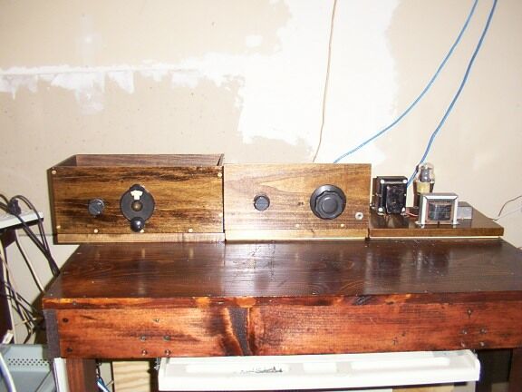
Here is a picture of the complete 1929 station.
2-tube #30 regenerative receiver is to the left, the #10 triode Hartley
transmitter in the center and the power supply on the right. I typically use
a battery pack to power the receiver which is not shown. Knife antenna switch
and key are not shown either, I do not currently own an old time key, and just
recently put a knife switch together and mounted it to a small stained board
to match the rest of the station. I am going to build a homebrew key.
During the Dec 2000 AWA 1929 contest, I used split antennas to work 10
stations with this rig
I didn't try very hard to win the contest,and didn't
work everyone on the band,
but I wanted to see for myself that an old time
rig such as this can be effective.
Here is the contest log for the contest.
December 9, 2000
| CALL | RST | QTH | NAME | TX TYPE and YEAR |
| VE3BBN | 559 | Ont | Dave | '29 Hartley @10 W |
| WA3FFC | 559 | PA | Scott | '27 MOPA @10 W |
| W2ZM | 589 | NY | Bob | '29 Hartley @9 W |
December 10, 2000
| CALL | RST | QTH | NAME | TX TYPE and YEAR |
| W2ZE | 559 | NY | Mike | '29 MOPA @ 9W |
| N2VON | 539 | NY | Dave | 29 Hartley @ 3W |
| VE3BBN | 559 | Ont | Dave | '29 Hartley @ 5W |
| KD3OR | 549 | WPA | Rob | '29 Hartley |
| W2irs | 559 | NJ | Lou | '29 Hartley @ 10W |
| K3DZ | 588 | WPA | Frank | '29 MOPA @10W |
| KE2O | 557 | NY | John | '29 TNT @5W |
Note: This page was modified from the original page, and trhe image work was not consistent. I do not presently have this transmitter, however I will be rebuilding it and the new Hartley will be featured.
BACK