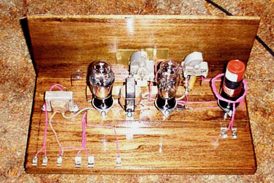
This radio was built using similar techniques as our grandfathers used to built their radios. The parts are assembled on a wooden base, however, I used some modern parts but tried to use whatever I could find from that era. More power to you if you have mid 1920's parts available. Connections are made using fahnstock clips, and the entire set is battery operated. A pair of D cells supplies power to the filaments and a 45 volt B battery powers the plates. 5- 9 volt batteries in series will work just fine if you cant find the real thing.
I began by preparing the base. A piece of
wood, 6 X 12 inches is cut. This can be pine or anything you may want
to use. Poplar is a nice wood to use as it takes stain better and the
grain will show better. Stain and varnish however you like it,
While youre working with the wood, you'll need to make a front panel as well,
I used a piece of wood that the store calls a "Hobby Board" measuring
6x24 inches, I cut it down to fit the FLAT part of the base, say, 11 inches.
This piece was only about 1/8 inch thick, and makes for a nice thin front
panel. Cut a piece of wood, maybe a 1/2 X 1/2 X 10. After both
boards are finished, I fastened the front panel so that the 1/2 X 1/2 is
flush with the bottom of the front panel on the inside of the radio using
small wood screws. Then fastening the 1/2 X 1/2 to the front of the
base also with screws. I put everything together temporarily to see
how everything fits. It will be taken apart later so you can drill
the holes for the 2 controls in the front panel later. Cut 2 pieces
of wood 1/2 X 1 inch each about 10 inches long. These will be your
tube mounts. They will be arranged like rails with the 2 tube sockets
between them. There will be 3 tube sockets mounted equally apart across
the rails. The first socket will be the coil socket, the other 2 for
the tubes.
Once you have the parts mounted, you mau have the parts mounted, you may begin wiring the radio. The only thing that is of any importance is that L1 and L2 must be wound in the same direction. Here is the schematic of the receiver.
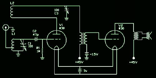
The output transformer is a typical tube type audio output transformer, available from a junk tabletop radio. The interstage transformer can be anything that has 2 high impedance windings. You want it to step up to the grid of the 2nd tube. I used an ohmmeter to determine which winding had more turns. You can also use another output transformer for the interstage by hooking the high impedance side to the first tube, then running a capacitor to the grid of the second (.01uF) and a 100K resistor from the second tube's grid to ground. You will not get as much volume this way, but it will work if you dont have the interstage transformer.
L-1 and L-2 can be found by experimentation, you can take empty pill bottles and 4 or 8 pin tube plugs and by winding the coils around the pill bottles and inserting them into the tube plugs. Make sure though that you get the right number of turns first before gluing the pill bottles down to the plugs. This receiver is general coverage, so the number of turns arent totally critical, but... the 2 windings MUST be in phase. L1 and L2 are both wound on the same form. L2 has about 1/4 to 1/3 the number of turns as L1, and the antenna tap is about 1/10 up from the ground end. A separate antenna winding can also be used, 2 or 3 turns wound over the cold end of L1 will work for 80 meters, 1-2 turns on 40, and 1 turn on the higher bands should you wind coils for them. What I did on my receiver for the antenna link is use reasonably stiff wire and a set of fahnstock clips directly under the coil, and wound the coil separately from the main coil so that it can be adjusted up and down the main tank to adjust the amount of coupling. It is crude, but it works for me. If you go that route, a 3 turn link will work fine for all bands.
Try about 25 turns for 80 meters. Half the number of turns to double the frequency, double the turns to reduce the frequency by half. 25 turns should allow you to cover the 80 meter band with the capacitor plates meshed at least halfway. You want the amateur band that the coil is designed for to tune with the plates meshed as much as possible. This gives slightly better bandspread. It also allows you to install a separate bandspread cap in parallel with the main tuning cap.

Connect power and
antenna and ground. The antenna should be as long a wire as you can
get, or you can use clip leads on your station antenna to connect to this
radio.
This radio operates slightly different than your "big rig".
C1 tunes the radio, and the tuning is VERY touchy, especially on
high frequencies. C2 adjusts "regeneration". Start with this
cap unmeshed. As you turn this cap to close it, you will find a point
where you will hear a click and perhaps some faint squeals in the headphones.
Now back this off to the point JUST BEFORE you heard the squeals. Tune
around and you should run across a broadcast station. Tune it in, and
adjust the regeneration capacitor (C2) for the strongest squeal free signal
you can get. You now have the radio set as sensitive as it will get
for AM reception. If you advance C2 until it just begins squealing
on the AM station, you can tune around and you will find some morse code
or single sideband stuff. The point where the detector just breaks
into oscillation (it begins squealing) is the most sensitive point for carrier-less
reception (SSB and CW).
You now have a very sensitive 2-tube regenerative receiver. Some enhancements may be to put a vernier drive on the tuning cap, a bandspread cap can be connected across C1 which will give you more control. A small 10 pf or so variable cap would work well for this. Another thought is you can feed the headphone output into a speaker amp. I've done that as well, and it works if you dont like wearing "cans" all the time. Experiment with ideas, I used my regenerative receiver as my main station receiver to operate 160 and 75 meter AM and SSB. It is DEFINATELY sensitive enough to actually use on the lower ham bands . Pair this up with a simple 1-tube #45 transmitter, and you have a complete homebrew vintage 1925 ham station. Perhaps I will build one and post an article on it as well.
Email
me
sometime and let me know how you enjoyed this article and if you built
the radio and how it works for you.
UPDATE:
I recently made a couple modifications to this receiver. First I added
a second audio stage consisting of a third #30 triode. This substantially
increased the audio output. This is a worthwhile improvement to the original
2-tube circuit.
Another change that I made was I changed the detector grid leak capacitor
and resistor. I changed the capacitor to 22 pf and increased the resistor
to 10 megs. This did improve the sensitivity and selectivity, but it may
have increased it too much. The large signal handling ability has degraded
significantly and I may change these values again. The receiver is not as
stable as it was with the old values. Perhaps splitting the difference
will be a good idea, leaving the capacitor at 47pf and increasing the resistor
to about 3.3 - 5.6 megs. I also found that it is a real good idea to use
a silvered mica capacitor there to keep the stability good.
I recently made a couple modifications to this receiver. First I added a second audio stage consisting of a third #30 triode. This substantially increased the audio output. This is a worthwhile improvement to the original 2-tube circuit.
Another change that I made was I changed the detector grid leak capacitor and resistor. I changed the capacitor to 22 pf and increased the resistor to 10 megs. This did improve the sensitivity and selectivity, but it may have increased it too much. The large signal handling ability has degraded significantly and I may change these values again. The receiver is not as stable as it was with the old values. Perhaps splitting the difference will be a good idea, leaving the capacitor at 47pf and increasing the resistor to about 3.3 - 5.6 megs. I also found that it is a real good idea to use a silvered mica capacitor there to keep the stability good.
BACK