R-2000
BFO Adjustment Mod
Submitted by Terry
NOTE: Please read this entire article before attempting any modifications or adjustments.
The stock factory BFO is adequate for "normal" SWL activities. But I do quite a bit of FSK reception and found the compromises made by Kenwood created some problems when going from LSB to USB. There was a several hundred Hz difference that caused me to have to retune to verify mode.
I replaced the fixed value of 27pF with a silver mica fixed 20 and an adjustable 5.6~18pF. The fixed value was determined by experiment and was about 5 pF higher then I predicted. I tried a 15pF but could not achieve the desired adjustments.
First, adjust the BFO in
USB first.
Next, adjust to 456.7000
KHz
Then, switch to LSB and adjust to 453.3000 KHz
The CPU shifts the LO +/-
1.7 KHz for USB/LSB reception and this requires the BFO be adjusted to
match.
I had access to laboratory
instruments and found the adjustments quick and easy to do.
Without a very good quality digital frequency counter, I think you could use WWV (5, 10 or 15 MHz) during the quiet (nothing but the second ticks) period. Tune to 10.0000 USB. Since the last 50Hz is not displayed make sure that you are tuned to 10.0000 and not 9.0005 or 10.005 MHz. F-Lock the radio to prevent accidental detuning.
First, adjust for zero beat.
Next, go to LSB and adjust
for zero beat.
Then, go back to USB and
verify there was no shift.
In my R2000 there was no
shift.
If the LSB BFO frequency can not be adjusted to the proper value the parallel fixed capacitor is likely to be the wrong value. In my case I could not get the BFO low enough in frequency which meant I needed more capacitance. If the BFO will not adjust high enough, then the parallel cap is too large. Try 5pF steps.
As with all modifications this is an "at your own risk" project. Unless one does a lot of SSB work, this mod is likely not worth the time and trouble. I present it here for those few SWLers who might benefit from this.
It took me slightly over an hour to remove the circuit board and remove the old capacitor and replace it with the two new capacitors. To change the 15pF to a 20pF took about half that time.
If one has access to a lab grade frequency counter the first step is to readjust the 36MHz (9MHz*3) master oscillator. DO NOT attempt this unless you are certain your frequency counter is properly calibrated!
First, remove the upper and
lower case halves.
Next, connect the power
source.
Then, turn on the R2000
and allow it to warm up for at least an hour. For maximum
accuracy,
have the room within 10 degrees F of the temperature in which it will
normally
be used.
Next, connect the
frequency
counter to TP4. This will be found at the rear of the logic/PLL board
next
to the LO2 coax connector.
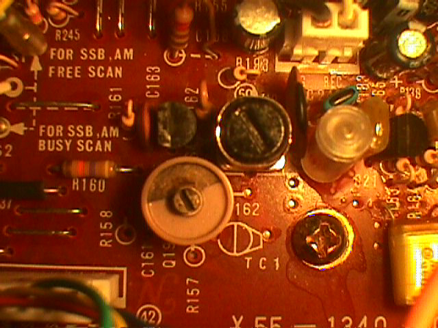
Finally, adjust TC1 in the
rear most metal box. It is a SMALL trimmer capacitor and should be
adjusted
with a small plastic
alignment
tools. Easy does it. It should not be far off adjustment.
Suggestions, comments, corrections or additions may be emailed here.