VARIABLE VOLTAGE POWER SUPPLY
Cost estimate: $10-$20
Here is an economical, versatile, and easily constructed power supply that is useful for
many applications. There are lots of versions of power supply circuits that use the LM317
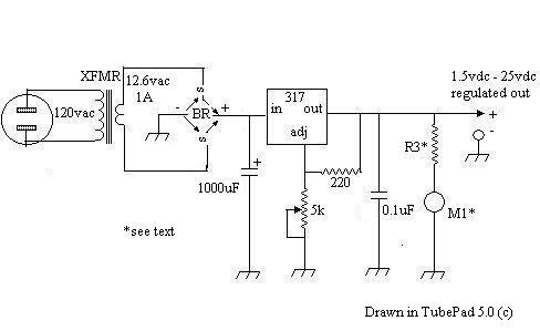
1.5-37vdc, 1.5A adjustable
voltage regulator available in literature and online; I have built two with the
circuit shown below and they have lasted for many years with no problems: one with a standard
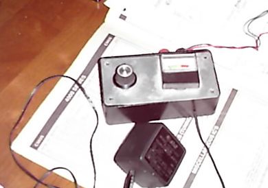
power transformer and one using a 120vac-to-13.5vac 'wall' transformer (shown in photo above left)
I was lucky enough to have in my junkbox.
For QRP radio amateurs, one of these can supply power for an entire station; including any transmitter
described or mentioned on this site (the adjustable
voltage allows increases above the 'usual' 12vdc for transmitters that can tolerate it), PLUS the
15-meter converter, PLUS my "station controller"; with enough power left over for more accessories
(I've used it to power a receiver but find that batteries generally offer more satisfactory
performance for my homebrew receivers and transceivers).
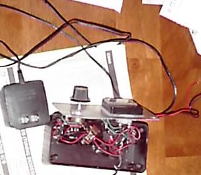
Construction Notes: There are so few components that they can be wired point-to-point without
a board, but mounting the LM317 on a tiny piece of perfboard or prototyping circuit board
does make it easier to solder. Meter M1 can be any microamp or milliamp meter configured to
display whatever fullscale range in volts is desired by calculating the value of
associated resistor R3 using Ohm's Law:
R= E/I
or
required_resistance_in_ohms = desired_meter_fullscale_range_in_volts / existing_meter_fullscale_range_in_amperes
(Since this selection of components yields an adjustable range of 1.5-25vdc I selected a 27vdc fullscale meter range, but this is up to the builder)
--Use at least a 1-amp transformer.
--A common inexpensive "6.3vac-0-6.3vac" power transformer is great for this; the center tap is not used.
--The selection of bridge rectifier is up to the builder's discretion: I selected 2A/50PIV to be cautious.
--The electrolytic capacitor can be any value 470uF-4700uF.
--The resistors are 1/2W to be on the safe side, but 1/4W resistors will probably be fine.
--A case, AC cord, output cord or insulated wires, perhaps binding posts, and knob for the 5k potentiometer finish it.
Operation: Plug completed unit into AC outlet and adjust R5 for desired DC output
voltage reading on your configured meter. If possible, verify output voltage with a multitester or voltmeter.
..need parts?...
***HOME***