|
A guide to building an inductance meter
| 
|
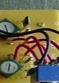
Yes the
rainbow inductance meter does work as shown in the ARRL Handbook’s of the
last few years: but you must pay attention to its construction! If you
homebrew it on a prototype board, or Manhattan style on a copper board you
will need to keep the wires to the H/L switch, and inductor jacks short and
play with R3 if it won’t calibrate properly — I used a 500 ohm trim pot in
place of a fixed resistor for R3 in my version of the device. (I wound up
with 127 ohms for R3, while another builder homebrew 1 wound up with 300
ohms) My unit reads from 2.2 uh up to at least 4.5 mh I don’t know if it
reads higher since I don’t have any bigger inductors to test with. |
|
After some
playing around with R3, I discovered that when its to high or to low you
will not be able to calibrate the high range to read properly with a large
inductor (lets say 4.5 mh) as you turn R6 it will peak at some point and
then start to decrease, its at this point you need to start turning R3 until
you get a bit over the inductor value. Now go back to R6 and back it down a
bit so that both the high and low scale will read about the same for a value
like 390 uh (390 on the low scale, and 39.1 on the high scale). By setting
R3 to its final value this way you take into consideration your lead length
and the resistance of the wire to the inductor terminals
Keep in mind
that in order to get the right frequencies out of the feedback oscillator
your C1, and C3 capacitors need to be very close to the exact values given.
It also helps to try a few different kinds of capacitors, ceramic disc, and
polyester both seemed to work ok, but the square chip kind didn’t have much
oscillation in them. After I tried few different kinds of .01, and .001
bypass caps’s I settled on the green polyester kind that put the oscillators
in the right frequency range. |
| |
|
| 
|
You must be able to hit 60 kHz on the low scale and 6
kHz on the high scale (on pin 3 of the hc132.) If you can’t hit those
frequencies as you turn the respective trim pot’s then either the capacitors
you are using are not up to par, or due to your layout you have too much
resistance in the feedback loop, so try a different capacitor, or, as in my
case, lower the 22k’s in the feedback loops to about 15k and see where your
at.
I put mine in a tin case made from ducting panels that
I bent against the edge of a work table; if you’re going to use a metal case
be sure the case is grounded to the batteries negative lead. (If you don't
ground the case, your reading’s are going to be screwy; since instead of a
ground plane, the case is acting like an antenna and interacting with the
inductor)
I
found these other links of people who have built it, and calibrated it
successfully kit1 , homebrew 1, and the rainbow kit can still be ordered
from here for $14.95 if you don't have an interest in making your own pc
board, and hunting down the parts, an getting it calibrated with all the
construction issues
|
| |
|
 |
Since I
managed to get a few free samples of the 74hc132 as a Hanukkah gift, I
decided to see if it was possible to use the SMD version of the chip with
out having to etch any copper boards. I eventually had the idea to cut off
the edge connectors of old computer PCI cards which have a .50 pin spacing,
just like the SOP package that I had. Eventually after some super glue, and
a tiny chisel tip on my 20 watt soldering iron, I managed to get the chip
soldered down to the edge connectors. All that was needed now was to get
some wires connected to the other end of those copper traces. After some
more trial and error, I decided to take apart some 22 gage stranded wire and
use each of the strands as a wire from the copper traces to the proto board |
| |
|
|
| |
|
|
| |
|
|
| |
|
|
| |
|
|
|