![]()

Interfacing a Maxtrac, Maxtrac 50, Maxtrac 100, Maxtrac 300, Radius M100, M214, M216, mobile to a TinyTrak3 Plus GPS position encoder for APRS.
The TinyTrak3 Plus is a great little piece of engineering. Plug and play and your ready to go! On this page I will show you how to interface it to some of the most popular Motorola mobiles being used for this and many other purposes.
First some notes on the TinyTrak 3 Plus:
Whether you purchase a complete unit or order the kit you need to make some changes to it during assembly or open it up to make them on a complete unit.
R5 - Replace this resistor to increase the audio output level, they recommend either replacing this 220k with a 100k or a jumper to increase the audio output. I found it was necessary to install a jumper. A 100k resistor kept the level too low even with R6 set to maximum. I took a piece of resistor lead and bent it into a "U" shape and soldered that in place of the resistor. That gave plenty of audio to properly set R6. Follow the instructions in the TinyTrak 3 Plus manual for setting the output level, you will hear a noticeable and quick decrease in the output while listening on another radio and adjusting R6 while sending the test tones as described.
R8 - This resistor just needs to be left out when the TinyTrak is used to key a radio via the PTT Out line.
R9 - You can leave out this trim pot when using the Carrier Detect line. It's used to set the carrier detect sensitivity when using the receive audio input for carrier indication. Or you can install it and set it to center if you wish to leave it in for later use with other radios, etc.
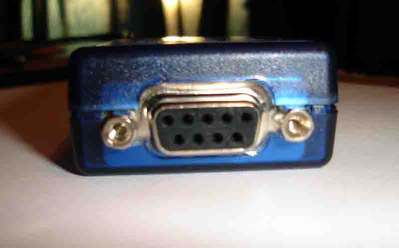
The TinyTrak 3 Plus uses a female DB-9 for the radio connection and a male DB-9 for the gps receiver input. They do not have the hold-down screws for the mating connectors however and I felt it necessary to fix that, in a permanent mobile installation having those connectors just sitting on there loosely could cause problems later. A slight modification to the bottom half of the plastic case with a dremel tool on a low speed with a multi use cutting bit takes care of it. The screws can be installed in the connectors included with the TinyTrak by using some machine screw nuts. As you can see in the picture you just orient them so the flat of the hex head meets the top half of the case.
Radios with 16 pin logic boards:
Radios that have the 16 pin accessory connector on the back of the radio can be programmed via RSS to supply all the signals needed. Pins 4, 6, 9, 8, 12 and 14 can be assigned in the RSS.
The accessory connector shell part number is Digi-Key Part Number 104422-1-ND, made by AMP Corporation as their part number 104422-1. AMP makes a wide variety of contacts for this shell with varying wire sizes and plating types. The one most appropriate for 22 AWG wire is Digi-Key Part Number A3007-ND ( AMP 1-87309-3) And these pins are gold plated!
The first thing to take care of on a 16 pin radio is programming. To get to the RSS screen shown below you must first read the radio, then from the main menu hit F4 for the Change/Create/View menu, then hit F2 for the Radio Wide menu, then hit F9 for the Other Accessory menu.
For the TT3P we will set Pin 8 to CSQ Detect and select Active Low. All other options will be disabled.
The terms Active High and Active Low for the "Active Level" options in the RSS can be misunderstood, resulting in major confusion. Active Low means that the pin is normally floating, and is pulled to ground when the function is true. Active High means that the pin is normally pulled to ground, and is allowed to be switched high when the function is true.
Just use the enter key to move around, it will highlight each item as its selected and you use the up and down arrows to change each selection. All the functions can be set for low or high. So if you need an active low or active high COS/COR just set it here and you are done, no radio modifications or hardware changes are needed to go from one to the other. This is why the 16 pin radios are more desirable, everything can be done via RSS to match the controller being used.
The radio to TT3P cable should be wired as follows:
| Radio Accessory Jack Pin # | TT3P DB9 Pin # |
Function |
|
3 |
3 |
PTT |
|
5 |
1 | TX Audio |
| 7 | 6 | Ground |
|
8 |
2 | Carrier Detect (COR) |
|
11 |
5 | RX Audio * |
|
13 |
7 | B+ |
|
15 & 16 |
NOT USED | Internal Speaker Enable ** |
* RX Audio is not needed by the TT3P if you use the Carrier Detect line for channel activity.
** If left open the internal speaker will be disabled, beneficial since you don't need to listen to the activity.
Radios with 5 pin logic boards:
With a couple internal modifications all connections needed for the TinyTrak3 Plus (hereby referred to as the TT3P) can be made through the mic jack. You can use the RX Audio available at the mic jack for channel activity, however I prefer to feed the TT3P with a COR signal from the radio for Carrier Detect.
The first thing that is needed is a Carrier Detect signal for the TT3P, this is accomplished the same way as interfacing the Maxtrac to a repeater controller.
Since the 5 pin logic boards are not capable of being programmed for all the signals needed a minor modification is necessary to bring COR / COS out - in this case to either pin 1 or pin 2 of the mic connector. The following modification will give you a low going COR / COS using the audio mute signal from the CPU. By the way, pin 1 of the mic connector is located on the top end of the connector (nearest to the volume control). Note that 900 MHz MaxTracs have the components that implement HearClear (a noise reduction technology based on a compandor circuit) mounted on the microphone jack / volume control circuit board in the control head.
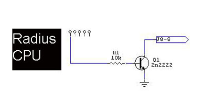
To add a COR circuit to a MaxTrac / Radius mobile the only parts needed are a 10k resistor, and a common NPN transistor, for example a 2N2222 or a 2N3904. In the text and drawings below this new transistor is called Q1, not to be confused with any Q1 in the radio.
First thing you need to do is disassemble the radio. This involves removing the Torx head screws, two each side, and the two holding on the front panel. Remove the front panel first and then remove the bottom cover. With the front panel facing you look for the radios CPU, left half of the board towards the rear of the radio.
There are several varieties of the 5 pin logic board and there is a slight difference between the Radius M-100 and Maxtrac radios as well. Refer to the two following pictures showing the CPU and connection locations for the two varieties.
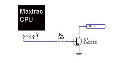
Connect to the locations as shown here in the following picture depicting a Maxtrac HLN9123A (the most minimal logic board).
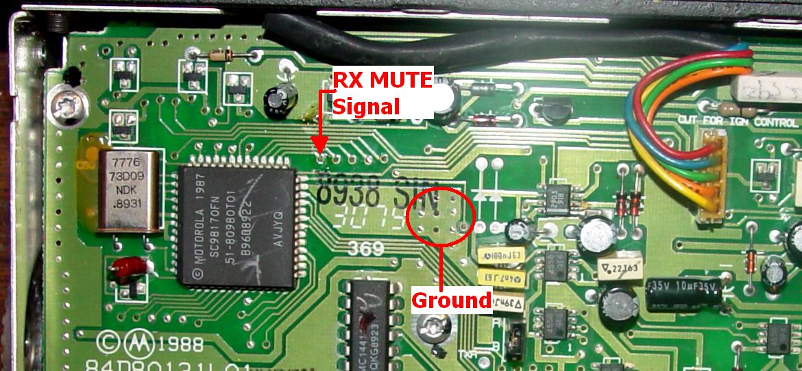
You need to remove the solder masking from the through hole for one end of the 10k resistor. Solder the other end to the base lead of Q1. Remove some of the solder masking from the board's ground plane and solder the emitter of Q1 to it, keeping it above the board slightly. Just like building dead bug style. The floating collector lead will be used in the next step.
Note: Before making the connection to J8 leave the front panel connected and verify with an ohmmeter that you have a connection from pin 1 of the mic connector to a pin on J8. As said above, on the 900MHz radios the pin 1 and pin 2 mic jack pins never leave the front panel switch board and you will have to tap onto pin 1 or 2 there.
Then from the collector of the new transistor run a small gauge wire to J8. Pin 1 of the mic connector is on pin 8 of the J8 header, counting right to left with it oriented as shown in the picture, Pin 2 of the mic connecter is on pin 9 of J8. COR will now be available on pin 1 or pin 2 of the mic jack. Until now both pin 1 and 2 of the front panel microphone connector is unused.
The way I set it up is to use Pin 1 to supply switched power, on and off with the radio power switch, to the TT3P, and Pin 2 to for the low going Carrier Detect, COR. Run a jumper from the collector of Q1 to J8 Pin 9. Using a small fuse, I used a Pico fuse that is the size of a 1/4w resistor, install a jumper from J8 Pin 5 which is SWB+ from the radios volume control power switch to J8 Pin 8. Pin 1 and 2 on the radios mic jack are available to be reassigned however you choose though.
The radio to TT3P cable should be wired as follows:
| Radio Mic Jack Pin # | TT3P DB9 Pin # |
Function |
|
1 |
7 |
B+ |
|
2 |
2 |
Carrier Detect (COR) |
|
3 |
NOT USED |
|
|
4 |
6 |
Ground |
|
5 |
1 |
TX Audio |
|
6 |
3 |
PTT |
|
7 |
NOT USED |
|
|
8 |
5 |
RX Audio * |
* RX Audio is not needed by the TT3P if you use the Carrier Detect line for channel activity.
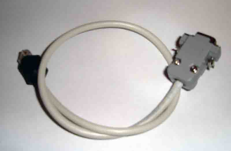
An example of a completed cable, of course you could make it whatever length you choose as well. I used a short length of network patch cable and installed a Maxtrac mic cable dust boot over the RJ-45 plug before installing the DB-9 on the other end.
![]()