
If you have a radio with a dead logic board, this information is helpful in replacing the dead unit, but will not give you all the information needed for repair of that dead logic board. If the old logic board is unresponsive when attempting to collect all the tuning information via RSS and a RIB then you will need to replace the logic board from scratch and that will require a service manual and the correct test equipment to do a full alignment of the radio.
If you're stuck with a radio that has one of the less desirable 5 pin boards, or you want to fully upgrade a two channel radio with parts salvaged from an 800 MHz Maxtrac, then read on!
First of all, I will be referencing the channel upgrading article often, so please go read that article first for all the background information needed here.
Basically the procedure is simple. Get a cheap 800 MHz Maxtrac that has a 16 pin logic board and a full feature front panel. Buy a new full feature escutcheon to replace the trunking type labeling of the front panel buttons, see the upgrade article for escutcheon part number, and if the new board doesn't have a version 5.34 firmware prom you will need that as well. Now you have all the pieces necessary to upgrade a low feature 2ch Maxtrac.
First, before you do anything, verify the operation of the 800 MHz radio! Unless you have a nice collection of test equipment, at least see that it powers up normally! Take the covers off, visually inspect the logic board, make sure its not a water logged corroded radio that was tossed aside, a common problem with some cheap surplus units from eBay.
If all is well then you need to connect the radio to the RIB and run Maxtrac Lab. Since we are not interested in the tuning information from the 800Mhz radios RF board you can use the upgrade article as a reference and skip to the blanking procedure without recording any information. At this time all we are interested in is creating a blank and ready to be re-used 16 pin logic board. Leave the 800 MHz firmware in it for the time being, it's not an issue until we are ready to reinitialize it!
After blanking the board remove it from the 800 MHz radio. This is very simple, but you do need some Torx bits to remove the screws. To disassemble the radio remove the two screws on both sides, and then remove the two front panel screws. Pull the front panel off, you will not be able to totally remove it yet due to the speaker connection that goes back under the cover, usually two gray wires. Pull off the top and bottom covers, and then disconnect the speaker lead from the logic board and the two main front panel connectors from the logic board pins. Set aside the front panel for now, we will get back to that shortly. Disconnect the white connector near the speaker connector that goes to the PA.
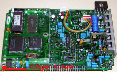
Now remove the small shield on the logic board to reveal the firmware prom and the one screw hidden under that shield. There is six screws going through the logic board, one is longer than the other five on some radios and is located in the front left corner. You also have two screws going in from the right side into the heat sink on the logic board. Now you need to carefully remove the logic board from the chassis. I have heard many opinions on this, the way I generally do it is to just carefully start to wiggle it free, it has pins that go through the chassis to the RF board on the top side of the radio. If you have trouble getting it to come free use a plastic adjustment tool, or wood, something that won't cause damage and gently work it between the Logic Board and the chassis from the front and free the board slowly, don't go wild prying on it! Now you have a 16 pin logic board that is blank and ready to be re-installed in any low band, VHF or UHF Maxtrac, the same board does it all!
Now take the radio that will be receiving the new blank logic board and follow the instructions on the upgrade page to record all the tuning information from the board you will be replacing. Once that's been done remove the logic board and install the blank 16 pin board. Replace all the screws and connections.
If the new board does not have the proper firmware then remove the old prom (conventional or trunking), and install the version 5.34 prom (HLN5569A). Before connecting and installing the front panel replace the escutcheon, or you can always go back and do it later after you know you have a working radio. To replace the escutcheon remove the four screws holding the display board into the front panel, then remove the buttons. You will see on the replacement escutcheon that there are two pins; if you look inside the front panel you will see them coming through, just take a small pin or Philips screwdriver or other suitably sized tool and tap on each pin to remove the old one. The new one just press fits into place. You can put a drop of glue on each pin if you're worried about vibration causing it to fall out of place, but they were never glued in originally and I doubt it will be an issue as these radios rarely show up without the escutcheon unless it was removed.
Now follow the reinitializing info in the upgrade article to setup the new 16 pin logic board.
If the radio that you've just upgraded is a UHF radio that you wish to use on the 70cm ham band then be sure to give the "Moving a 449-470 MHz Maxtrac to cover the 440-450 MHz Amateur band" article a read here!