
This article describes one reliable, simple, and universal method of interfacing MaxTrac, Radius, and GM300 series of Motorola mobile radios to common repeater controllers. Most of this information also applies to radio interfaces that are used with IRLP or EchoLink.
Purpose:
Scott KB�NLY already has a very good article that covers this topic in some detail, but it seems that a lot of people, many of whom should possess enough knowledge (judging by their 1x2 or 2x1 call-signs and lifetime ARRL memberships) to extrapolate the information presented by Scott, are unable to do so, hence the need to write something even simpler.
There are at least two methods that can be used to connect repeater controllers to MaxTracs (I'll use this generic name from now on to cover all varieties of this radio): the method proposed by the author, and the method you - the reader - end up using. There are an unknown, yet sufficiently large, number of interested readers on our planet; I'm not forcing you to use any particular method, but as this is simple, works, and requires very few external components, there's no reason to fight it. If you don't have, or want to buy the detailed service manual for the radios, or don't understand or wish to learn the workings of the electronic circuits, then you should appreciate the time and effort that went into collecting all of the information presented in this article.
Available Signals:
The MaxTrac has interface signals brought out via the 5- or 16-pin accessory jack on the rear of the radio, and the 8-pin RJ45 (MIC) jack on the front of the radio. You can also solder wires directly onto the logic board and bring them out any opening you can find; however there are no openings unless you remove part or all of an accessory connector, leave the covers off, or drill through the chassis and/or a cover. I'd rather not butcher a nice radio.
Unfortunately, the 5-pin and 16-pin accessory jacks are quite different. They do not provide all the signals a repeater controller needs, may require additional programming, and use unique plastic bodies and metal contact pins. Luckily, the front panel MIC jack is present on EVERY MaxTrac-family radio, and cables and connectors are relatively easy to come by - simple computer network cables can often do the job. Because the MIC jack is universal, this is the method I use. Doing so also eliminates the need to program the 16-pin accessory jack for the functions you'd need for your controller. There are enough possible combinations that you almost have to be a Motorola employee to understand them all. Why fight with it when there's a simpler means of getting the job done.
So, now that we've given up on the accessory jacks and decided to use the front panel MIC jack, here are the signals the stock radio provides:
| Pin | Signal Name | Description and Usage Notes (see note below) |
|---|---|---|
| 1 | PB1 | Spare, not connected, not wired on 900 MHz |
| 2 | PB2 | Spare, not connected, not wired on 900 MHz |
| 3 | Hook | Mike hang-up line; 5VDC; ground for PL/DPL receive |
| 4 | Ground | Logic and audio ground |
| 5 | MIC Audio | TX audio input; 9.6VDC; use blocking capacitor |
| 6 | PTT | TX PTT input; 5VDC; pull to ground to TX |
| 7 | SCI+ | Serial Programming Interface line - do not use |
| 8 | Handset Audio | RX audio output, fixed-level |
Here's how the RJ45's pins are oriented on the front panel of a Radius radio. Click on the image for a larger view:

The MIC jack shares a circuit board with the front panel volume control and power switch, as well as the Hear-Clear circuitry on 900 MHz radios. One single cable runs to a connector on the logic board: P8. For VHF/UHF/800 MHz radios, this is wired as shown below:
| VHF/UHF/800 MHz Radios | ||
|---|---|---|
| Logic Pin # |
Front Panel or Logic Board Use |
MIC Pin # |
| 1 | Volume Ctrl Top | |
| 2 | Volume Ctrl Wiper | |
| 3 | Keyway - no pin/wire | |
| 4 | Handset Audio | 8 |
| 5 | Switched DC to radio | |
| 6 | Incoming DC | |
| 7 | SCI+ (programming) | 7 |
| 8 | PB1 - Spare | 1 |
| 9 | PB2 - Spare | 2 |
| 10 | Ground | 4 |
| 11 | PTT | 6 |
| 12 | MIC Audio | 5 |
| 13 | Hook | 3 |
On 900 MHz radios, a Hear-Clear hybrid module is mounted to this circuit board, and microphone and receiver audio signals are routed through it. These radios use the pins slightly differently. Note that the spare pins on the RJ45 jack (pins 1 and 2) are not wired to anything. If you wish to use these pins, you will need to add your own wire underneath the circuit board, as shown in a later section:
| 900 MHz Radios ONLY | ||
|---|---|---|
| Logic Pin # |
Front Panel or Logic Board Use |
MIC Pin # |
| 1 [1] | Volume Ctrl Top | 8 |
| 2 | Volume Ctrl Wiper | |
| 3 | Keyway - no pin/wire | |
| 4 | Not Used - available | [2] |
| 5 | Switched DC to radio | |
| 6 | Incoming DC | |
| 7 | SCI+ (programming) | 7 |
| 8 | 9.6VDC | |
| 9 | Hear-Clear Enable | |
| 10 | Ground | 4 |
| 11 | PTT | 6 |
| 12 | MIC Audio | 5 [3] |
| 13 | Hook | 3 |
[1]: Audio on this pin comes from the logic board, runs through the Hear-Clear module, then appears at the top of the volume control. The handset audio signal is obtained from the top of the volume control. Functionally, this is the same signal as found on a VHF/UHF/800 MHz radio.
[2]: Add a wire from this pin to the MIC jack pin 1 or pin 2. See the text below for details.
[3]: Incoming audio from the microphone goes through the Hear-Clear module, then out to the logic board.
Specifics of the MIC jack signals:
All audio levels were measured with a Fluke 189 true RMS digital multi-meter using a sine wave input or modulating signal of 400 Hz.
The HOOK signal (pin 3) rests at 5VDC and needs to be pulled to ground to allow coded squelch. This can be done with an open-collector transistor or a dry relay contact. It supplies about 1mA of current and a 2.7k resistor to ground activated this signal on my radio. The threshold voltage is about 1.7VDC. If nothing is connected to this pin, or it's allowed to float high, the receiver will be in carrier-squelch mode. Do not pull this line to a higher voltage or you may damage the radio.
The ground signal (pin 4) is the same as the incoming DC and chassis ground. This is a common return for all other input and output signals.
MIC audio input (pin 5) needs about 50mV per 1 kHz of deviation on a VHF/UHF/800 MHz MaxTrac. Limiting kicks in at about 200-250mV. Pre-emphasis is always applied to audio fed into the MIC jack.
On 900 MHz radios, 50mV of audio produces about 0.3 kHz of deviation. Voice audio produces a lot more deviation for the same input level and the radio I tested had been adjusted to produce a maximum of 2.5 kHz of deviation with a very loud whistle. These levels will change if the Hear-Clear function is enabled. Pre-emphasis is always applied to audio fed into the MIC jack.
9VDC at 10-15mA is present on the MIC audio input (pin 5) to power microphone preamps. Your repeater controller may or may not like this DC voltage, or it may have a capacitor in series with its audio output to the transmitter. If one is not present, you will need to add a 10uF 16V electrolytic capacitor, with the positive lead pointing towards the radio. The input impedance is around 600 ohms.
Some radio interfaces may not provide enough transmit audio to fully modulate Motorola radios. They're designed to work well with Japanese radios where the input impedance is higher and the MIC input is a lot more sensitive. Many times, you will have to play with resistor values in the interface to produce more transmit audio or drive the 600-ohm impedance MIC input. Many Motorola base stations have similar MIC input qualities.
The PTT line (pin 6) rests at 5VDC during receive. It needs to be pulled to ground to cause the radio to transmit. This can be done with an open-collector transistor or a dry relay contact. It supplies about 1mA of current and a 2.7k resistor to ground activated this signal on my radio. The threshold voltage is about 1.7VDC. Do not pull this line to a higher voltage or you may damage the radio.
The handset audio output (pin 8) will run around 670mV on noise on a VHF/UHF/800 MHz MaxTrac, then it's about 600mV per 1 kHz of deviation. This level is independent of the setting of the volume control. De-emphasis is always applied to handset audio.
On 900 MHz radios, noise runs about 640mV, then it's about 630mV per 1 kHz of deviation. This level is independent of the setting of the volume control, but it will be different if the Hear-Clear function has been enabled. De-emphasis is always applied to handset audio.
Repeater Controller Requirements:
Besides a source of 12VDC power, most repeater controllers can get by with a minimum number of input/output connections:
- Receive Audio - audio from the receiver to the controller
- COR - Carrier-Operated-Relay - indicates a receive signal is present
- Transmit Audio - audio from the controller to the transmitter
- PTT - Push-To-Talk line to activate the transmitter when grounded
- Ground - common to all signals
All of these except the COR signal are available on the radio's front panel RJ45 MIC jack. Fortunately, that signal can be easily added.
It may be handy some day to have the ability to disable the PL/DPL requirement on the receiver. The MIC jack's HOOK signal can be used for this purpose. Normally this line is connected to ground by the microphone when it is placed in its hang-up bracket; this enables PL/DPL receive, if the radio is so programmed. When the mike is removed, the radio reverts to carrier squelch because the HOOK line is now ungrounded. You can connect an output port from your repeater controller to ground this line for PL/DPL receive or let it float for carrier squelch. If you don't have or need this controller capability, then you must be sure to ground the HOOK signal when wiring the system if your repeater will utilize coded squelch. Even when grounded, you can still over-ride this function by using the front panel MON button: press it to toggle the radio between carrier and coded squelch, or hold it in to open the squelch. Just remember to set it properly when you leave the repeater site. If you will never need this feature, you could add a jumper wire on the back of the RJ45 connector to connect pins 3 and 4 to permanently put the receiver into coded squelch mode, regardless of the HOOK signal.
Some radios can be programmed to ignore the HOOK signal, eliminating the need for you to ground it externally or via your repeater controller. Look in the RSS screens for an option that mentions "hang-up box" or 'HUB".
Logic Board:
The logic board on these radios is underneath the radio chassis. On MaxTracs and Radiuses, two separate cables connect the logic board to the circuitry on the front panel (one cable handles the display and push buttons, the other feeds the MIC jack and power and volume control) and a separate two-wire speaker cable handles speaker audio; on GM300s, the speaker wires are built into the cable that attaches to the logic board. You can see the twisted pair of gray speaker wires in the logic board photo below.
While there are several different part numbers for the various logic boards, they really fall into two categories as far as interfacing is concerned: those with masked CPUs and those with EPROMs. The masked CPU logic board is recognizable by the single, large, 40-pin IC soldered onto it and no shield around the microprocessor area. The term "masked" means that the program (firmware) is built into the CPU chip during its manufacture; they literally "mask" the appropriate components according to the functions the chip is to perform. You can not replace the firmware on a masked logic board unless you replace the CPU chip. Here's a photo of a masked logic board. Click on the image for a larger view:

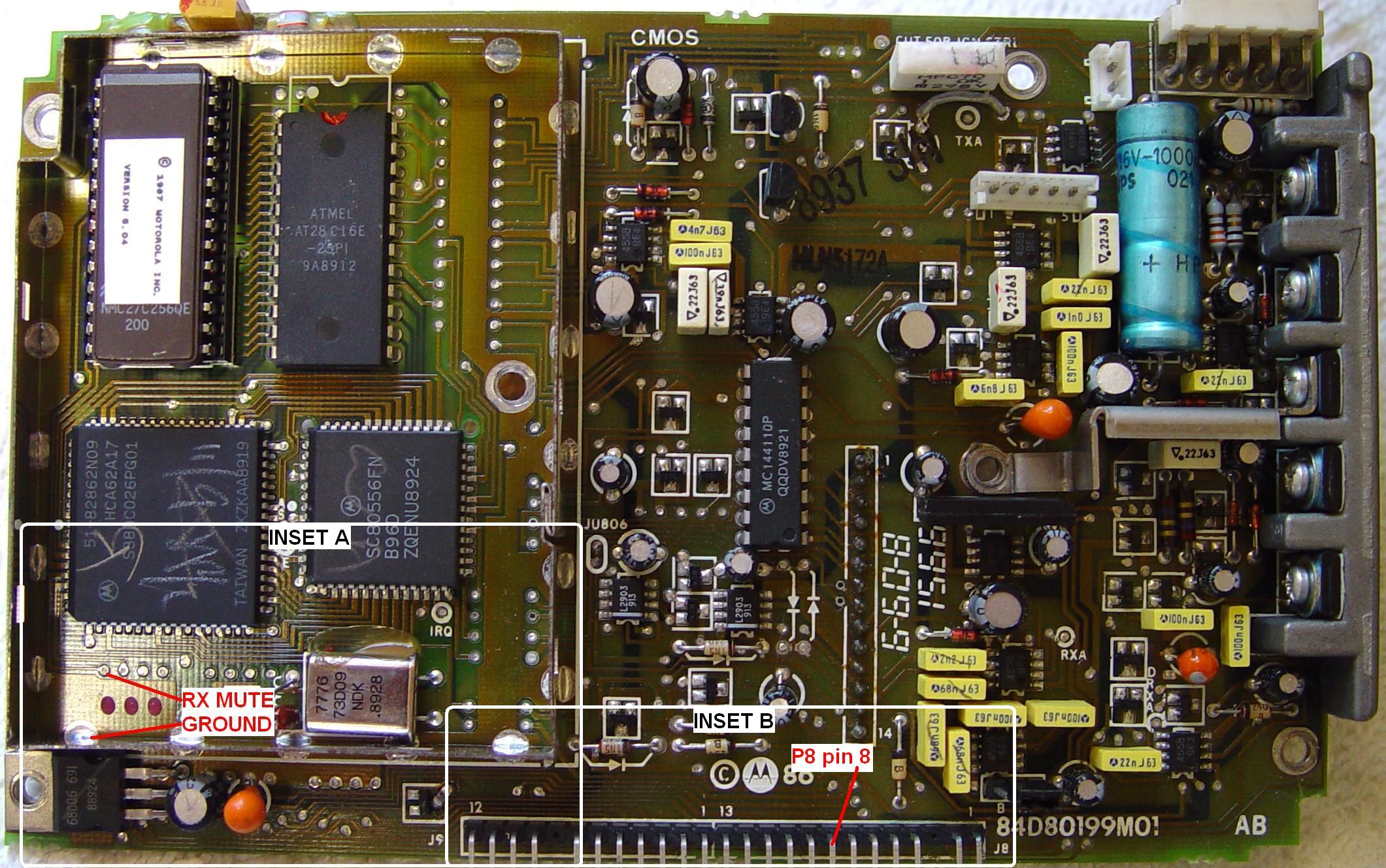
The other variety uses a socketed EPROM to hold the program (firmware) and encloses the CPU and its support chips in a shielded area on the left side of the logic board. There are different EPROMs for different purposes, usually trunking vs conventional. All 900 MHz logic boards have 16-pin accessory jacks, shielded microprocessor areas, and replaceable EPROMs. Here's a photo of an EPROM logic board. Click on the image for a larger view:
I've found the following logic boards in my manuals, but the list is probably incomplete. Some of these logic boards are only used in trunking applications. "Pins" is the number of pins on the accessory jack. "Logic / EEPROM" is the style of microprocessor firmware and whether or not the board has external code plug EEPROM.
| Part # | Pins | Logic / EEPROM | Radios Used On |
|---|---|---|---|
| HLN9123A | 5 | Masked / NO | V/U/800 MHz MaxTrac/Radius |
| HLN8074E | 16 | Masked / NO | V/U GM300, 8ch, 2-layer |
| HLN5172A | 5 | EPROM / YES | V/U/800 MHz MaxTrac |
| HLN5173A | 5 | EPROM / NO | V/U/800 MHz MaxTrac/Radius |
| HLN5402C | 5 | EPROM / YES | V/U/800 MHz MaraTrac/M400 |
| FRN5529A | 16 | EPROM / YES | 900 MHz MaxTrac |
| HLN5173B | 16 | EPROM / YES | V/U/800 MHz Radius |
| HLN8070D | 16 | EPROM / YES | V/U GM300, 16ch, 4-layer |
| HLN9313A | 16 | EPROM / YES | V/U/800 MHz MaxTrac/Radius |
Finding a COR signal:
All of the signals most repeater controllers need can be obtained from the front panel MIC jack, except for a COR signal. The layout and connection points are quite similar for all boards of the same style board (masked vs EPROM). The signal we're looking for is called RX MUTE and it comes from the 68HC11 microprocessor on masked logic boards or the SLIC (custom gate array) on EPROM logic boards, both of which are soldered in. This signal is low (0.0 - 0.7VDC) when the radio is squelched, and high (4.0 - 5.0VDC) when the radio is passing audio.
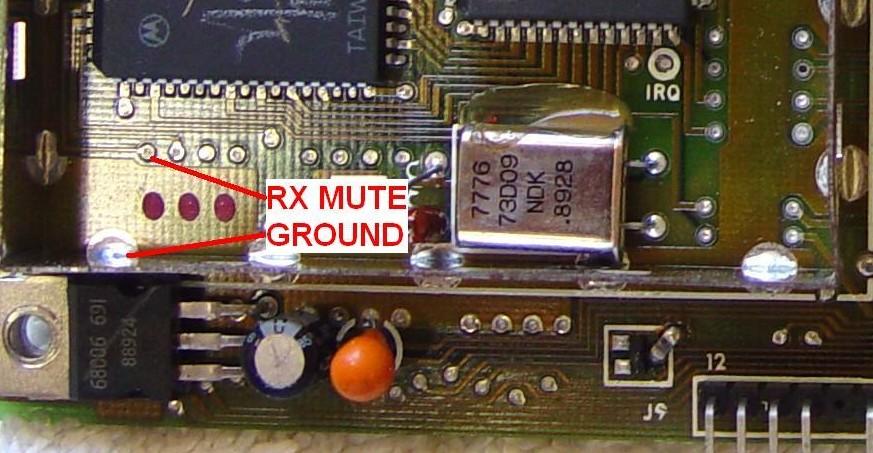
Here's a close-up of the RX MUTE signal area on a VHF/UHF/800 MHz EPROM logic board:
Here's the same area on a 900 MHz EPROM logic board. Note that the signal is in exactly the same location on all EPROM logic boards, even though the feed-through hole pattern is slightly different:

The masked logic board is the odd one. Here's a close-up of the RX MUTE signal area on that board. You can see some flux residue around the marked points; this is because I had a COR circuit installed in this radio at one time:

If this signal level (active high) is acceptable to you and your repeater controller, then use it as-is, but be careful you don't short it to anything else or attempt to drive it high or low from outside the radio, or you will destroy the logic board. This is a TTL-level signal and it probably can't provide more than a few milliamps of drive current.
If you or your repeater controller would rather use a signal that's active low, or if the current requirement is higher, then you need to add a simple signal inverter somewhere between the RX MUTE line and the outside world. This can be created with a 4.7k 1/4 watt resistor and any common NPN transistor, such as a 2N2222, 2N3904, etc. A schematic of how you connect these parts is shown below:

Parts placement isn't critical, but keep the leads shorter than 1/2 inch. Use some electrical tape or other insulation if necessary to keep these parts from shorting out nearby circuitry. The emitter lead can be soldered to any convenient ground point such as inside the shielded area on EPROM logic boards or to an empty ground hole on masked boards. The resistor attached to the base lead of the transistor goes to the RX MUTE signal on the logic board; the location of that signal is shown in the photographs above.
There is also a COR signal available inside the radio. This is a true carrier-only signal that comes from the receiver board and is inverted on the logic board to feed the microprocessor. This signal only cares if the receiver is squelched or not; it does not depend on the setting of the front panel MON button or the MIC jack's HOOK signal. Some situations may need it, so I am mentioning it here. I have found the RX MUTE signal to be much more useful. If you really want to use this, it's available on pin 2 of the connector that goes between the logic board and the RF board (pin 1 is towards the center of the board). The voltage on this pin is 0.0-0.3VDC with a carrier present, 3.75VDC with no carrier present.
Yet another alternative that can be used WITH LIMITATIONS is tapping to the collector of Q552. This signal is active-low and it is equivalent to adding the external transistor circuit described above. (You can find the location of this part in the Detailed Service Manuals; it controls the RX Audio Muting on the logic board.) However, Q552 is attached to other circuitry in the radio and as such the collector lead only goes up to about 4.5VDC. Depending on the external equipment that will be using the COR signal, you can connect to this directly or use an isolation diode (such as a common small-signal 1N914 or 1N4148) pointing towards Q552. You need to be aware that this COR signal will be pulled to ground if the radio loses power, and the external equipment may not pull this line higher than 5VDC. Due to these restrictions, it's just as easy to build the two-component COR circuit described above and not worry about any of these issues.
Bringing the COR signal out of the radio:
Once you have the COR signal, you need to get it to your repeater controller via the front panel RJ45 MIC jack. It's not hard to do, but it depends on the radio you're working with. You need to make three choices:
- Determine which logic board you have (masked or EPROM)
- Decide which pin you'll be using on the RJ45 MIC jack for the COR signal (pin 1 or pin 2)
- Choose whether your controller needs the inverted signal or not
Follow the appropriate step for your radio below:
- VHF/UHF/900 MHz logic board: Attach a piece of
insulated wire, or bare wire with sleeving over it, to
J8 pin 8 or pin 9. I find it easier to unplug P8 from
the logic board to gain access to the end of the pin
closest to the logic board. Route this under the CPU
shield if possible, or out the lower right corner so
the shield cover (on EPROM boards) will fit back over
the wire. Run the wire up towards the RX MUTE point on
masked boards. Here's a close-up of the logic board
connectors:

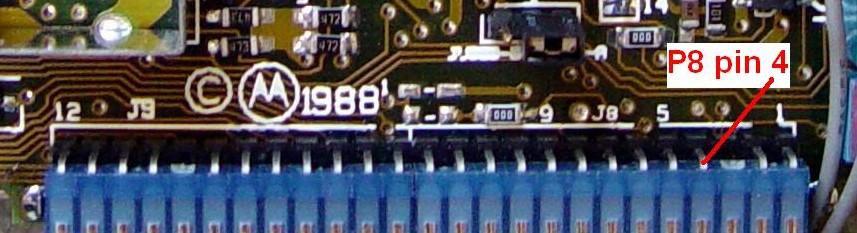
- 900 MHz logic board: Attach a piece of insulated
wire, or bare wire with sleeving over it, to J8 pin 4.
I find it easier to unplug P8 from the logic board to
gain access to the end of the pin closest to the logic
board. Route this under the CPU shield if possible, or
out the lower right corner so the shield cover will
fit back over the wire. Remove the MIC/VOL/PWR circuit
board from the control head and add a short wire from
the lead coming from the logic board connector pin 4
(these are silk-screened on the other side of the
circuit board) to the RJ45 jack pin 1 or pin 2.
Motorola wired all the connector pins between the plug
and circuit board, so you only need to add your own
wire from the wire coming from pin 4 over to pin 1 or
pin 2 of the RJ45 MIC jack. Refer to the photo below.
Then replace the MIC/VOL/PWR circuit board. Here's a
close-up of the logic board connectors:
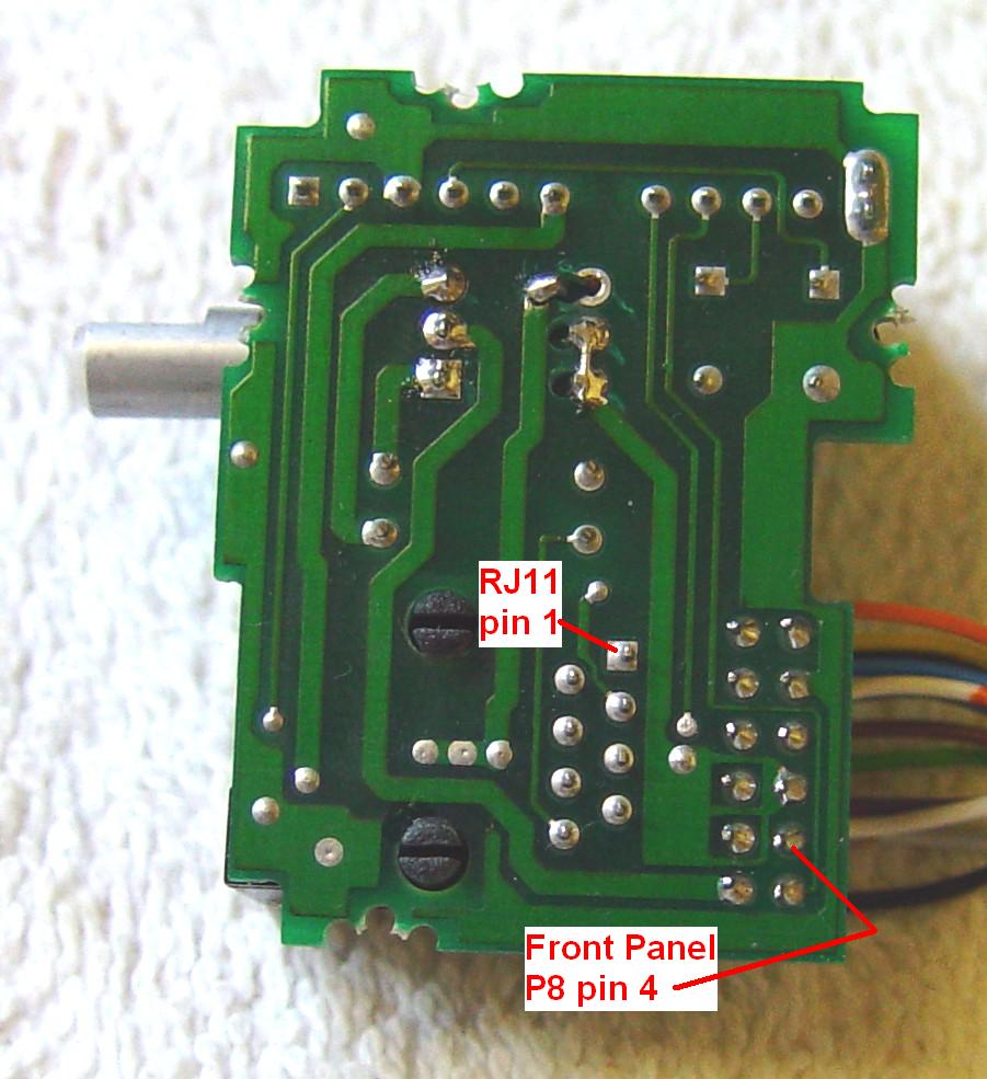
Here's the back of the MIC/VOL/PWR circuit board. Note that the volume control has been replaced on this unit, hence the additional holes visible in the photo:
Now choose one of these procedures:
- For an active low COR signal, obtain the 4.7k resistor and NPN transistor to build your own COR signal inverter. Cut the resistor leads to about 1/2 inch length. Solder one end into the appropriate RX MUTE hole on the logic board. Solder the other end to the base lead of the NPN transistor. Solder the emitter lead of the NPN transistor to a GROUND point on the logic board. Attach the wire you ran above to the collector lead of the NPN transistor. Put some electrical tape around the transistor leads to keep them insulated.
- For an active high COR signal, connect the wire you ran above to the RX MUTE hole on the logic board.

Kyle Yoksh K0KN submitted this method for VHF/UHF/800 MHz radios. He mounts the NPN transistor directly on the logic board's J8 connector. He solders the emitter lead to pin 10 (Ground) and the collector lead to pin 8 (SPARE), resulting in a more secure mounting method. The base lead still goes to the resistor and the RX Mute signal. This method can't be used as easily on the 900 MHz radios because J8 is configured differently. Kyle submitted this photo showing the transistor (a 2N3904) installed in a radio:

Making the final connections:
One simple repeater controller is the Computer Automation Technology CAT200B. I have three of these on my repeaters and have had great success and zero problems with them for over 5 years. This controller uses a DB25-style connector for all interface signals. Wiring to a pair of MaxTracs is very simple, and is shown in the table below. I use pin 1 for the COR signal on all of my radios.
| CAT Pin |
CAT200B Controller Signal Name |
TX Pin |
RX Pin |
|---|---|---|---|
| 13 | RX Audio #1 | - - | 8 |
| 4&6 | COR #1 & CTCSS #1 | - - | 1 [1] |
| 11 | TX Audio #1 [2] | 5 | - - |
| 10 | PTT #1 | 6 | - - |
| 17&18 | Ground | 4 | 4 |
| 14 | Switch #1 [3] | - - | 3 |
[1]: I use RJ45 connector pin 1 as my COR signal. You can use either pin 1 or pin 2.
[2]: A DC blocking capacitor may be needed in series with this signal; it depends on the repeater controller you use. One is NOT required with the CAT200B controller.
[3]: The wire from CAT pin 14 (Switch #1) to the receiver radio pin 3 (HOOK) is optional. When low or grounded, this requires the incoming carrier to have the proper PL/DPL code along with the received signal; when high, the receiver reverts to carrier squelch. If not used, ground pin 3 going to the receiver. This line is controlled by the CAT's Zone 4 Bit 5; when OFF, the pin is low, grounding the HOOK signal and enabling PL/DPL on the receiver.
When you make the RJ45 cables, be sure to label the ends so you know which one goes to the transmitter and which one goes to the receiver. The radios may not care, but the duplexer that's handling the RF signal definitely will.
If you end up using two identical radios for your repeater, it makes sense to program them the same and add the COR signal wiring to both of them. If the receiver or transmitter section has problems, you can just swap the radios and keep going. Also, it's wise to prepare a spare radio to be used if one at the repeater site dies.
The COR #1 and CTCSS #1 input lines on the CAT200B can be configured for active-high or active-low. When using the COR transistor circuit described in this article, these are set for active-low signals and you will need to add a pull-up resistor on the COR #1 line on the CAT200B. They supply 4.7k resistors for this purpose and the board already has empty holes for it. See the CAT200B manual for more details.
A Very Simple Cross-Band or Repeater Interconnection:
The following circuit can be used to connect a pair of radios as a repeater. It cross-connects the COR Output (pin 1) from one radio to the PTT input (pin 6) of the other and the Handset Audio Output (pin 8) from one radio to the MIC Input (pin 5) of the other. The HOOK Input signals are grounded on both radios, activating coded squelch (if programmed).
The capacitors remove the DC voltage present on the MIC Input pin, while the resistors lower the transmitter audio level. The positive lead of the capacitor goes towards the MIC Input on each radio. You can have this setup work in both directions by installing all the components and wires, or eliminate one resistor, one capacitor, and one wire for a unidirectional repeater (i.e., remove the components in red).
There are no timers or control mechanisms. An incoming carrier with the proper coded squelch (if the radio is programmed that way) will cause the other radio to transmit, and the audio will pass from one radio to the other. If you want a receiver to respond to carrier only, press the MON button on that radio. See the schematic below.
![]()