| Radio/Repeater Control Interface | ||||||||
| These
Are Small Images ([Right Click] The Image to see Larger Ones) |
||||||||
|
||||||||
Component Layout |
||||||||
The Components in this image
are in color. |
||||||||
Power for Relays Wiring Layout |
||||||||
Provides 12 VDC to Relays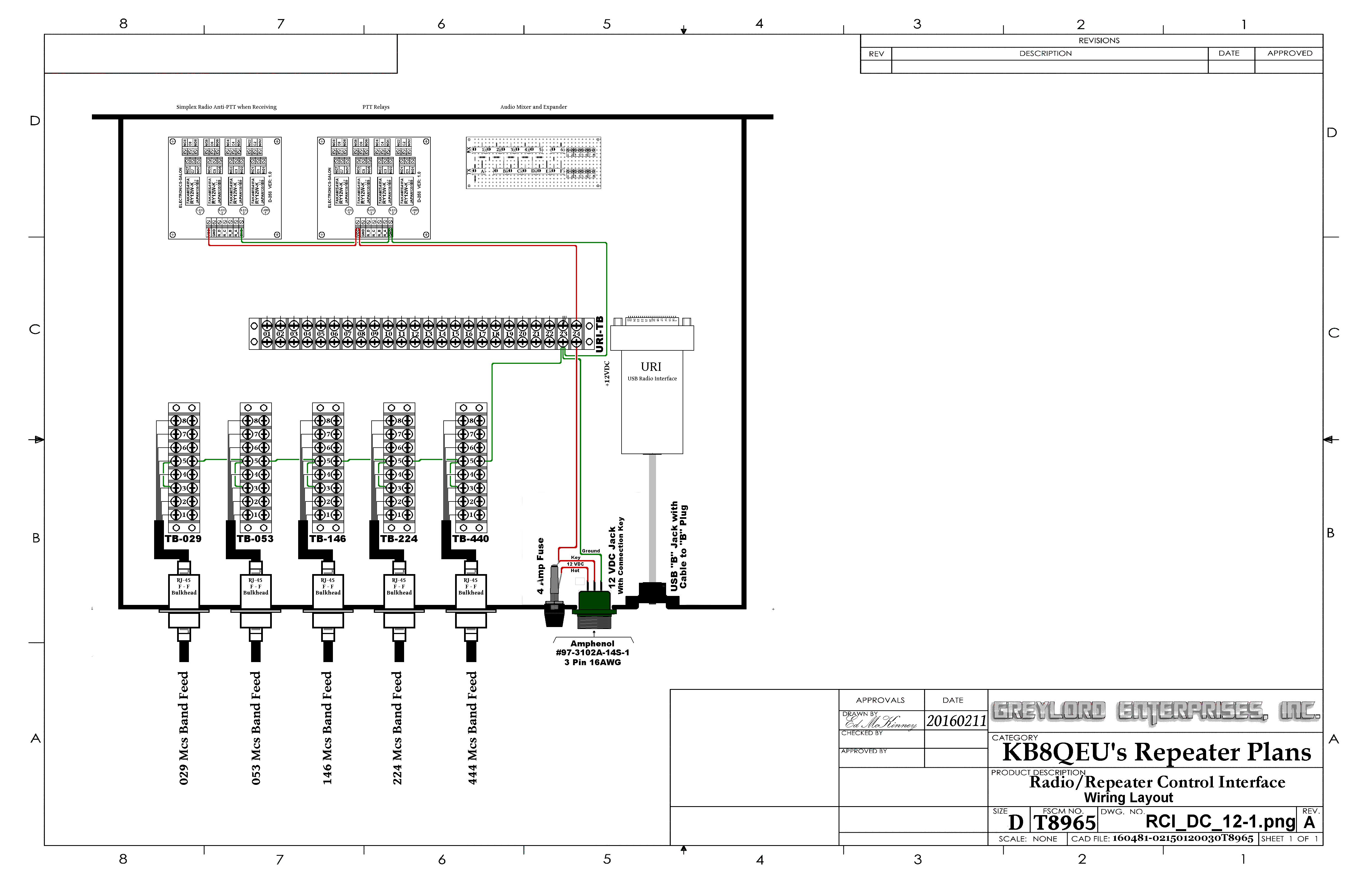 |
||||||||
USB to Radio Interface (URI) Wiring Layout |
||||||||
The Wiring of the URI to a
Terminal Block for Easier Hookups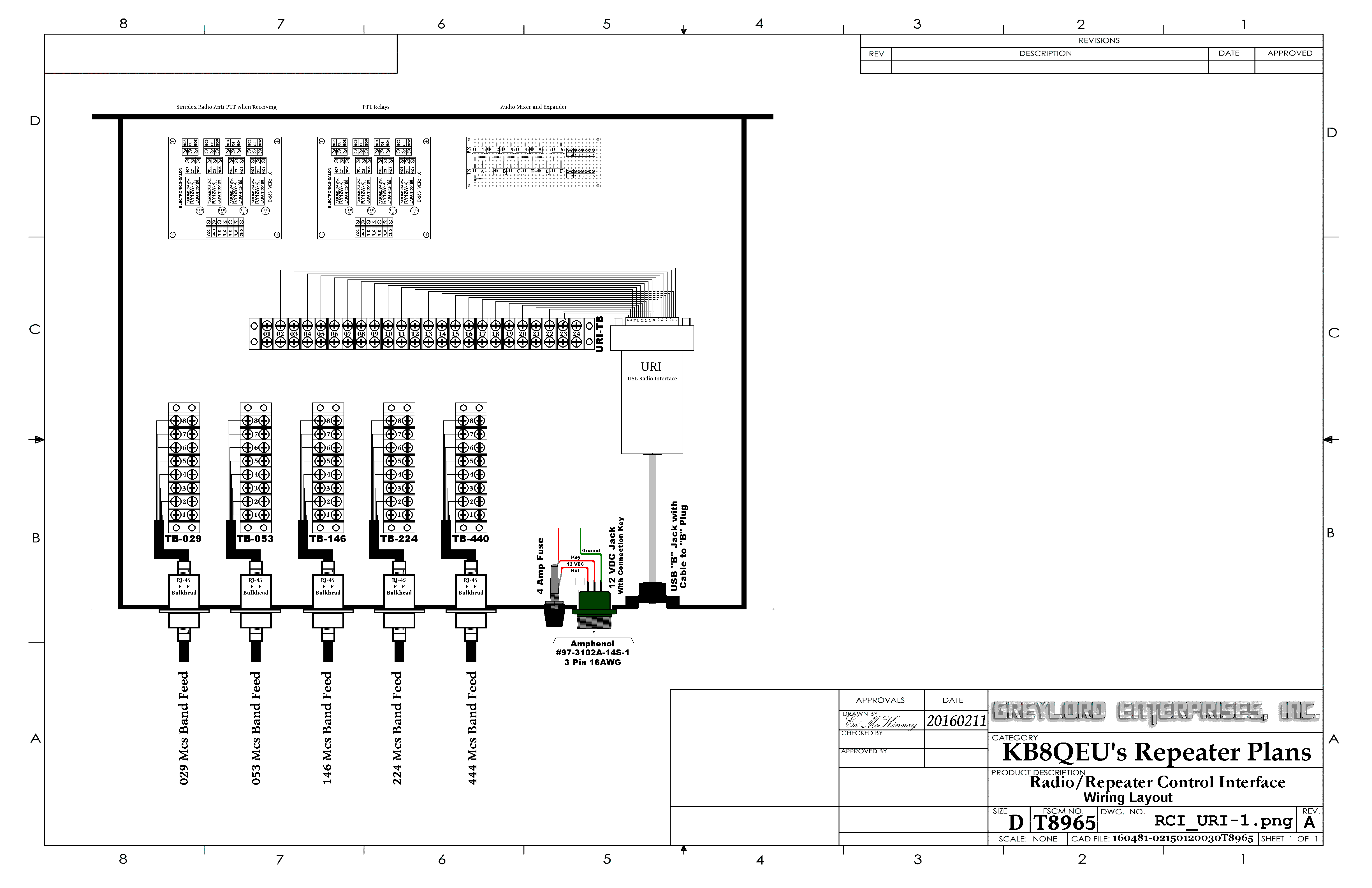 |
||||||||
TX Audio & RX Audio Wiring Layout |
||||||||
| The TX Audio Expander in Blue and The RX Audio Mixer in Red 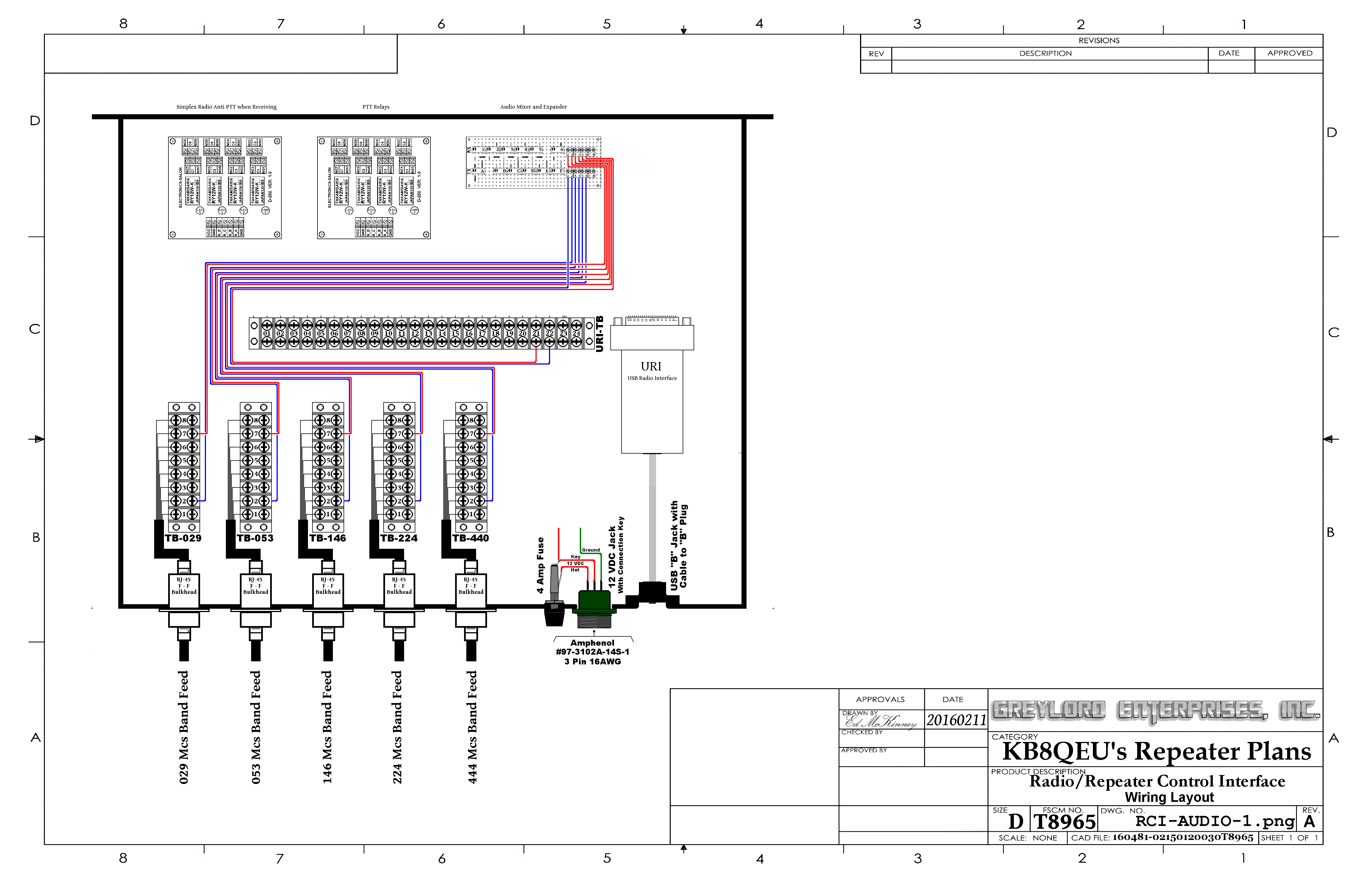 |
||||||||
PTT Wiring Layouts |
||||||||
| 029 Mcs. Band Remote Base / Simplex Node 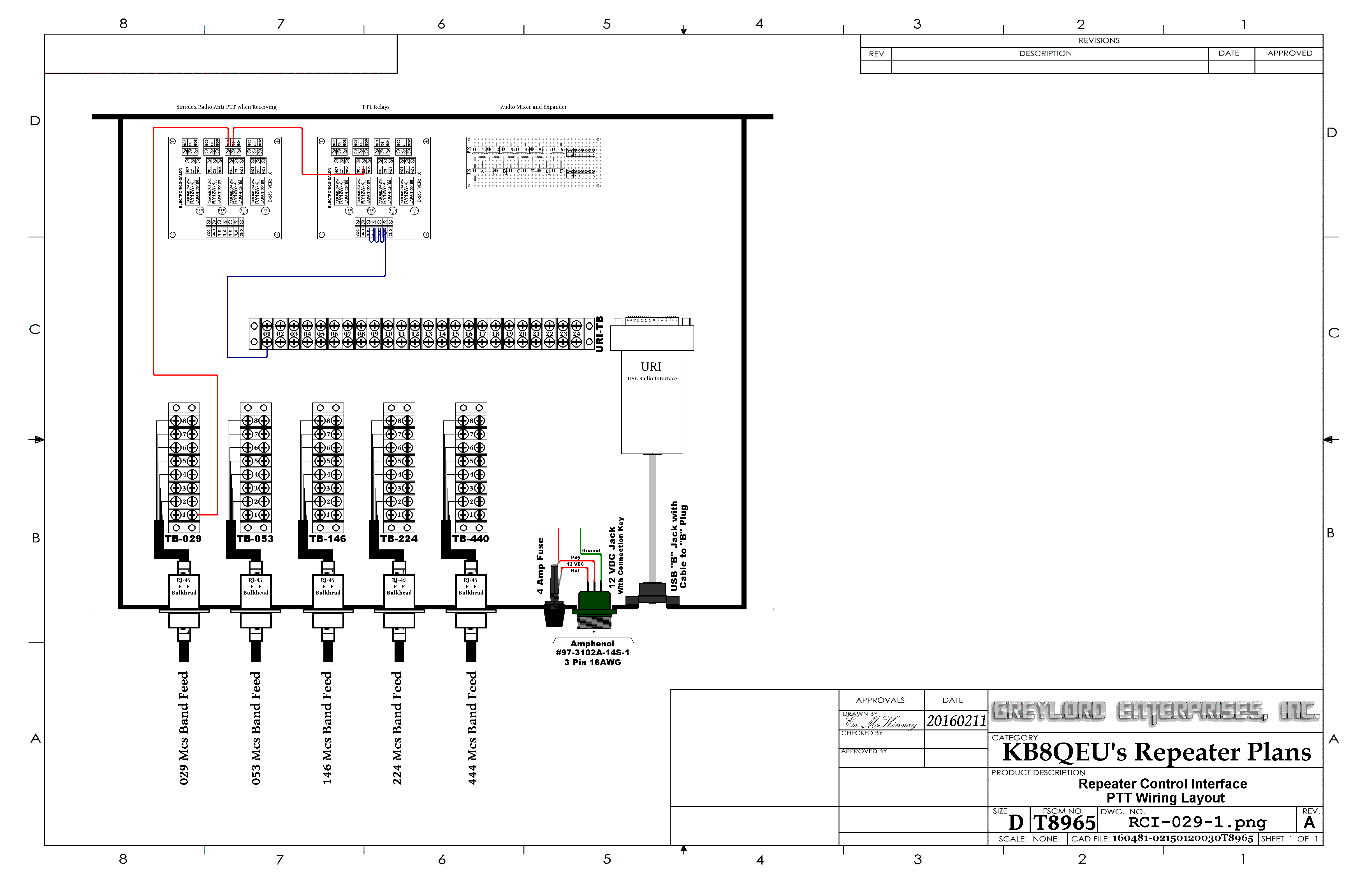 |
||||||||
| 029 Mcs. Band Repeater  |
||||||||
| 053 Mcs. Band Remote Base / Simplex Node 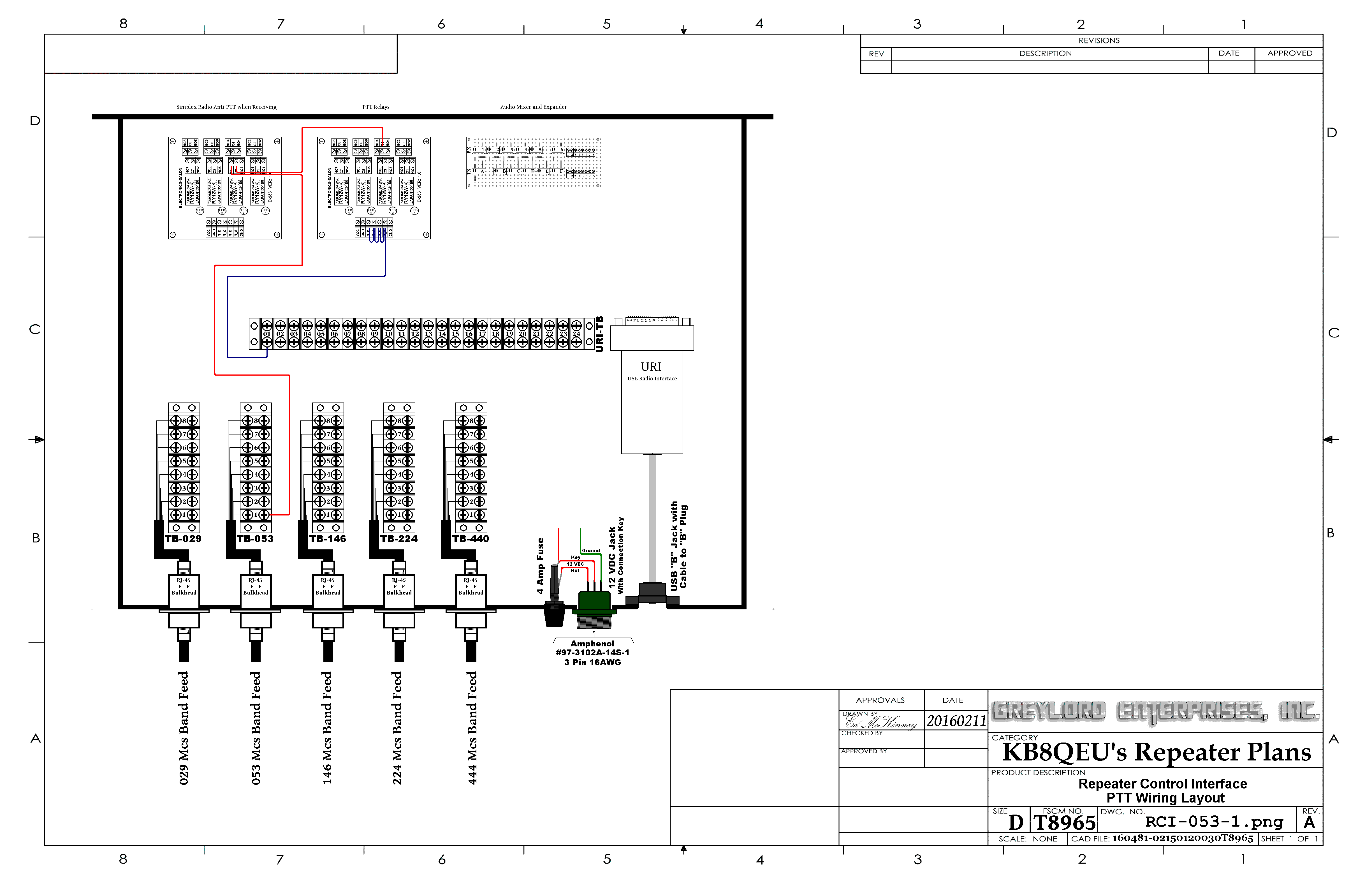 |
||||||||
| 053 Mcs. Band Repeater  |
||||||||
| 146 Mcs. Band Remote Base / Simplex Node 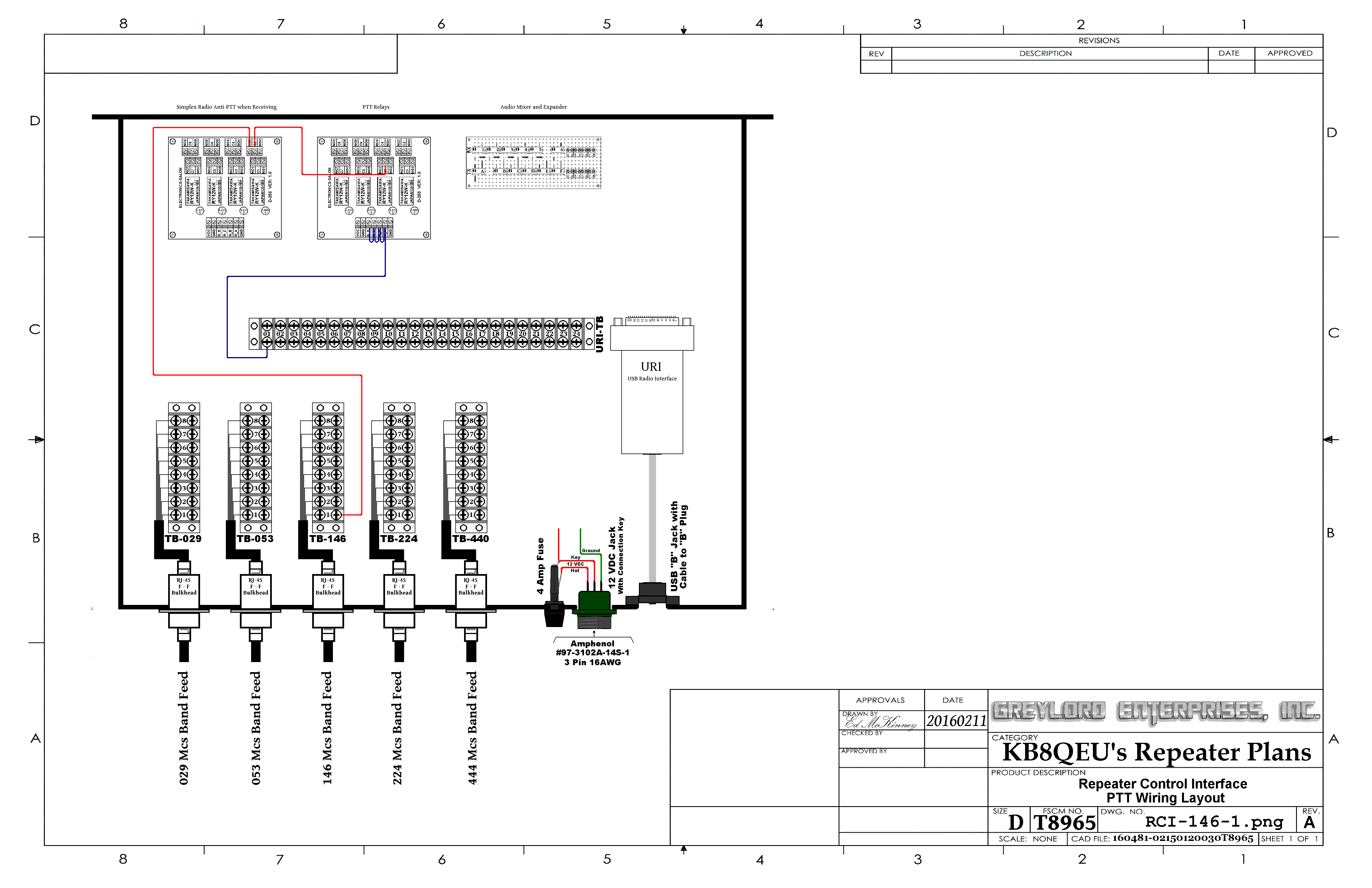 |
||||||||
| 146 Mcs. Band Repeater 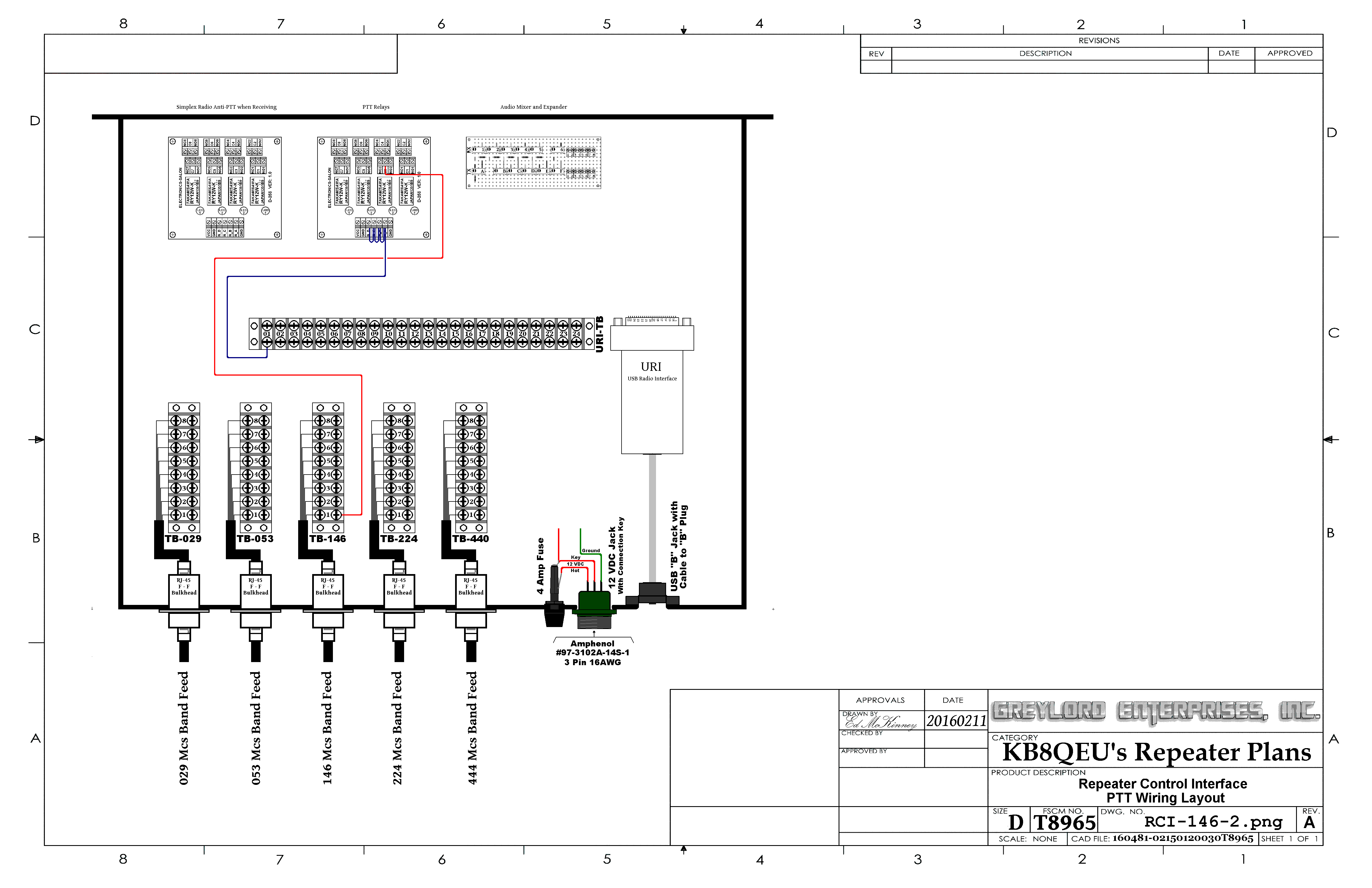 |
||||||||
| 224 Mcs. Band Remote Base / Simplex Node  |
||||||||
| 224 Mcs. Band Repeater  |
||||||||
| 440 Mcs. Band Repeater 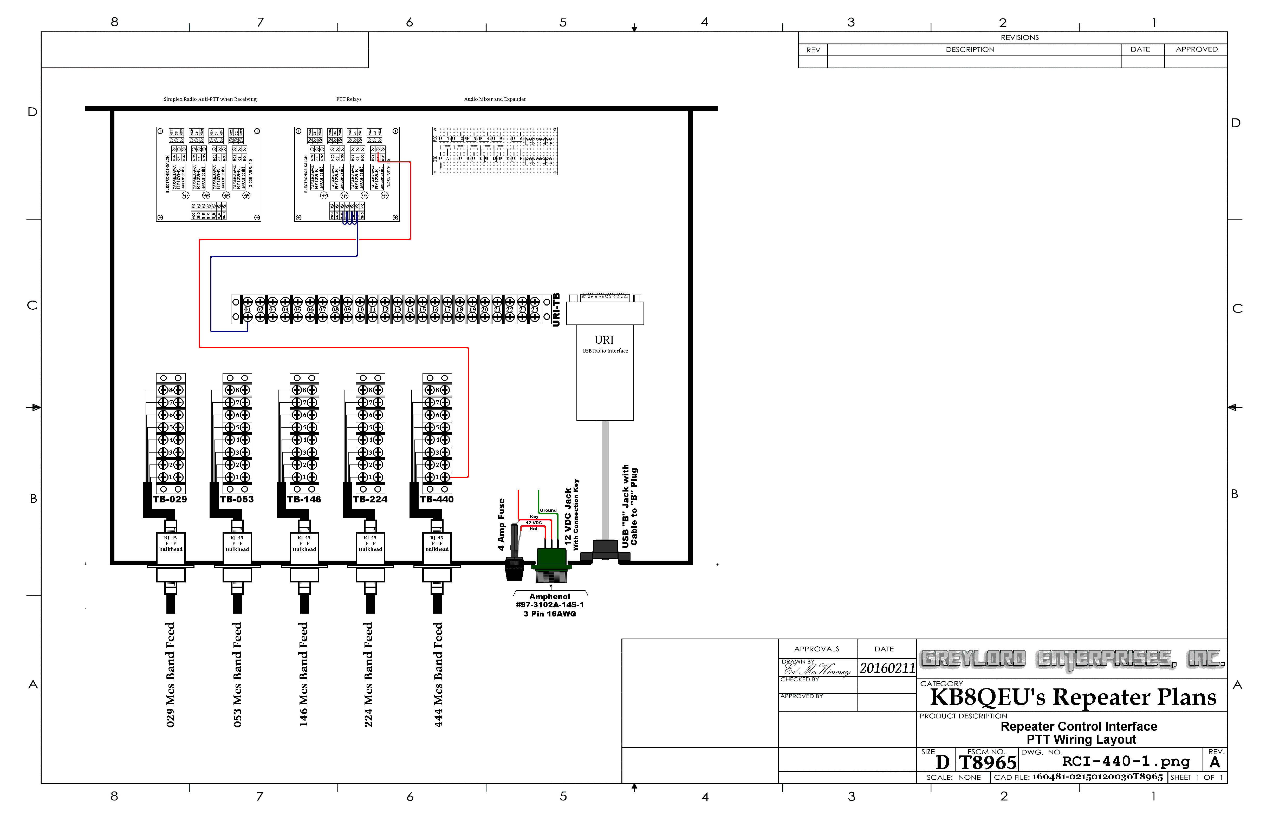 |
||||||||