7 Induced currents, a-c power, and equivalent networks
![]()
In this chapter the currents that flow in the circuit external to a vacuum tube as a result of electronic motion within the tube are considered. These induced currents are important in the application of tubes as circuit elements. An electron accelerating or decelerating under the influence of an electric field gains or loses kinetic energy. The source that provides the field loses or gains an equal amount of energy. Using the concepts of induced current and energy exchange we consider power amplification in a triode.
After studying the external electrode currents, we consider these currents in an external circuit. We introduce a method for the analysis of circuits using grid controlled tubes. It is found that a grid controlled tube driven by a small a-c signal may be simulated by a simple equivalent network containing an ideal voltage generator or ideal current generator as an active element. An equivalent network can be substituted for the tube for the purpose of analysis and the a-c currents that flow in the various circuit elements can be determined by Kirchhoff's laws.
7.1 Currents induced by electron motion
Let us consider what happens when a charge moves from one electrode to another. In Fig. 7.1 we show an isolated charge q in transit between planar electrodes A and B which are connected through a galvanometer. Because of this interconnection, charge cannot pile up on either electrode. It might be thought that no deflection of the galvanometer will occur until the charge strikes electrode B and flows back to A through the galvanometer. This is not the case. In reality, charge flows through the galvanometer while q is in transit between the electrodes, and the current through the galvanometer stops when the charge strikes electrode B. The current through the galvanometer is known as the induced current. Convection currents both in space and in wires are the currents normally discussed in this text [footnote omitted, rwc]. The induced current is equal to the rate of change of the charge induced on either electrode by the moving charge.
Figure 7.1 Currents between two electrodes, A and B.

The induced current which flows through the galvanometer does so because the moving charge q exerts forces on the free charges in the electrodes and in the wire connecting them, causing them to rearrange until the resultant electric field within the electrodes due to all the charges is zero. Figure 7.2 illustrates the electric lines of force originating on a single electron and terminating on induced positive charges on the surfaces of parallel plane conductors. The lines of force of the static electric field are not included. Note that there are more lines terminating on the conductor nearer the electron. In all cases the total effective positive charge (q + q' in Fig. 7.2) induced on both electrodes equals e, the magnitude of the charge of the electron.
Figure 7.2. The electric lines of force associated with an electron
between parallel electrodes.

The magnitude of the induced charge q' on the anode may be computed by equating the work done in transferring the induced positive charge from cathode to anode through the external circuit to the energy gained by the electron in its movement from the cathode toward the anode. The battery V0 effectively transfers a positive charge q' from cathode to anode as the electron moves from z = 0 to an arbitrary position z. The electron is acted on by a uniform electric field V0 / d, and a total work of
W = Fz = e V0 z / d (7.1)
is done on the electron. The battery does work V0 q' in transferring the induced charge; the induced charge in turn sets up fields which do the same amount of work on the electron so that
V0 q' = e V0 z / d (7.2)
or
q' = e z / d (7.3)
Thus we see that the induced charge on the anode grows linearly with distance as the electron moves from cathode to anode. The current associated with the changing induced charge is
i = dq'/dt = (e / d) dz/dt = e v / d (7.4)
This relationship is a fundamental one in the field of high-frequency devices. It is limited, however, to plane-parallel electrodes in the absence of space charge. The total induced current produced by a large number of (non interacting) electrons is the sum of all the individual contributions.
Note that the induced current I in equation 7.4 depends on the electrode voltages only insofar as the velocity v of the electron depends on these voltages.
We next find a general expression for the induced current flowing between arbitrarily shaped electrodes connected across a battery. Suppose an electron is moving with velocity v at a position where the electric field is . The work done on the electron by the field while the electron travels a distance ds is given by
-e ds (7.5)
The energy expended by the field in doing this amount of work on the moving electron is supplied by the battery as a small amount of induced charge dq moves through the battery. If the battery has a voltage V0, then the work done by the battery in moving the induced charge is simply
V0 dq (7.6)
Since these two energies must be equal, we have
V0 dq = -e ds (7.7)
Dividing both side of equation 7.7 by V0 and by the time dt required by the electron to move through ds, we have
dq/dt = - e / V0 ds/dt (7.8)
But dq/dt may be recognized as the induced current i and ds/dt as the velocity v of the electron, so we obtain for the induced current caused by an electron moving with velocity v between the electrodes
i = -e v / V0 (7.9)
This reduces to equation 7.4 for plane parallel electrodes.
Equation 7.9 must be modified if a continuous distribution of charge is present, so that
i = volume ( v / V0) dr (7.10)
From equation 6.5, J = v, so we may write
i = volume (J / V0 ) dr (7.11)
The integral is over the entire region occupied by current-density. J and are the current density and field at the volume element dr.
Example. We illustrate the preceding discussion by considering the current that flow in the three-electrode system shown in Fig. 7.3.
Figure 7.3 Currents in a three electrode system.

An electron, starting from rest at electrode 1, accelerates in a uniform field to the grid from time t0 to t1, but from t1 to t2 moves in the region between the grid and electrode 3 at a constant velocity. The induced current into the grid increases uniformly with time between t0 and t1, but is constant from t1 to t2 because v is constant (see equation 7.4).
While the electron is to the left of the grid, a total charge of e flows through the battery from the negative to the positive terminal, and the battery expends e V of energy in moving the induced charge. The electron gains this amount of kinetic energy from the field. The kinetic energy of the electron is converted into heat upon striking electrode 3, the heat energy being equal to the battery energy expended in accelerating the electron. While the electron is in transit, positive induced charge flows through the external circuit to electrode 3. This stops when the electron reaches 3. Note that the net charge (area under the i2 versus t curve) flowing to the grid is zero.
7.2 Current and power in external impedances
We now consider the effect of an external load resistance connecting two electrodes between which a d-c beam of electrons is passing. Figure 7.4 illustrates a beam of electrons passing through a grid and striking electrode P. if dN/dt electrons per second pass through the grid and strike electrode P and induced current I0 = (dN/dt) e will flow from ground through the load resistance R to meet the arriving electrons. A voltage drop of I0 R is developed in the resistance by this current I02 R. This power is supplied by the kinetic energy of the electrons in the beam.
Fig. 7.4. Parallel electrodes connected by an external load resistance

Since each electron in the beam faces a decelerating electrid field due to I0 R, it loses an amount of kinetic energy e I0 R during its flight from the grid to electrode P. (It is evident that I0 R must be smaller than the voltage to which the electrons have been accelerated in order that they reach P.) For dN/dt electrons per second the total power lost by the electrons in the inter electrode region is
e I0 R dN/dt = I02 R (7.12)
which is equal to the heat power dissipated in the resistance by the induced current. The remaining part of the electrons' kinetic energy is transformed into heat energy when they strike electrode P.
The present considerations are just as valid if R is replaced by a complex impedance Z. It is important to stress that in the model developed here the voltage i Z which develops across Z is not caused by the electrons which strike P and flow through Z. The induced currents flow only while charge is in transit between the electrodes. The positive charge that flows through Z is canceled when the individual electrons strike electrode P.
7.3 The extraction of power from a modulated beam
The control of energy or the conversion of one form of energy to another is of basic importance to our present-day technology. In this section we demonstrate how a change in beam current in an electron tube can provide a large change in energy in an external load. Since a change in beam current may require only a small expenditure of energy, as was seen in Chapter 6 for a triode, this process can provide the all-important control or amplification feature. Beam currents are often modulated periodically. In such cases the average power in a load in the presence of modulation is greater than the average power in the absence of modulation. This difference in power is called the a-c power. Since energy must be conserved and very little of the a-c power ordinarily comes from the a-c input signal, most of the a-c power must come from another source. In this case the source of energy is a battery or a d-c power supply which conveys power to the load via the kinetic energy of the beam as described in section 7.2.
We now consider the simple case in which the beam current I0 of the Fig. 7.4 has a sinusoidal modulation at an angular frequency . This may be obtained by varying the number of electrons passing the grid per unit time. The instantaneous current i may be written
i = I0 + I1 sin t (7.13)
where I1 is the amplitude of the current modulation. This current i develops in the resistance R a total instantaneous power P given by
P = i2 R = (I0 + I1 sin t)2 R (7.14)
Then the average power Pave over a complete cycle is found to be
Pave = I02 R + I12 R / 2 (7.15)
Note that this power is greater than the power I02 R in the absence of the current modulation. The additional power I12 R / 2 developed in the load resistance is called a-c power and is obtained from the kinetic energy of the electrons. To see qualitatively why the load power is greater in the presence of modulation, consider two half-cycles. When i is greater than I0, the number of electrons crossing the grid and the voltage drop across R are greater than average. Hence, in this case, more than the average number of electrons each lose a greater amount of kinetic energy than they would under d-c conditions. On the other hand, in the next half-cycle, less than the average number of electrons each lose a smaller than average amount of kinetic energy. As a result of the modulation the average over a complete cycle of the kinetic energy with which electrons bombard the collecting electrode is reduced and the energy which has been lost by the beam appears in the load resistance.
An important feature is that the induced current flowing through an external impedance Z is independent of the magnitude of the impedance provided that the electron velocity is not appreciably changed by the retarding voltage i Z. In many devices this condition is satisfied. Only the electrons in the space between the electrodes determine the induced electrode current. Modulating the beam causes and a-c power to be developed which varies linearly with the resistance (see equation 7.15). Since we can modulate the beam in a manner that consumes very little power, then, at the expense of the kinetic energy of the electrons and ultimately at the expense of the d-c voltage supply, we can develop a large a-c power in an output resistance, This is an important method for amplifying a-c power.
[discussion of klystrons, TWT's and magnetrons omitted, rwc]
 Fig. 7.5.
Electrode connected by load resistance and battery in series.
Fig. 7.5.
Electrode connected by load resistance and battery in series.
Let us reconsider the triode in the light of the present discussion. In a triode amplifier, the d-c supply is in series with the external impedance as shown in Fig. 7.5. The electrons have negligible velocity while passing through the grid and are accelerated toward electrode P by the battery. The induced currents pass through the battery as well as the series resistance, and power is transferred as before. The average power I0 V of the battery goes into the d-c power I02 R in the load resistance, the a-c power output I12 R / 2 , and the average power dissipated by the kinetic energy of the electrons as they strike electrode P. Thus
I0 V = I02 R + I12 R / 2 + Pave-mod (7.16)
When no modulation is present, or I1 = 0,
I0 V = I02 R + Pave-no-mod (7.17)
Substituting 7.17 into 7.16, we may write
Pave-mod = Pave-no-mod - I12 R / 2 (7.18)
Thus, the power dissipated as heat in the anode is reduced in the presence of modulation by the a-c power term. In fact, that anodes of high-power vacuum tubes are operated near their plate-dissipation limits may melt if the current modulation is removed.
7.4 Equivalent networks
Now that we have discussed the physics of induced current flow in the circuits external to a tube, we already to consider the representation of a tube as a circuit element. In the precious chapter it was pointed out that the current drawn from the cathode of a grid-controlled tube could be expressed as a function of the potentials of the grid and anode relative to the cathode and the tube parameters gm and rp. Equation 6.32 states
dia = gm dVg + (dVa / rp) (6.32)
In the special case in which the applied anode and grid voltages are modulated sinusoidally, the anode current will also be modulated sinusoidally. Using the notation of Chapter 6, where Ecc was the grid-cathode voltage with zero input signal and Ib and Eb were the corresponding "quiescent" anode current and voltage, we may write, for sinusoidal modulation at angular frequency
Vg = Ecc + eg sin t
ia = Ib + ip sin t (7.19)
Va = Eb + ep sin t
Here ip, eg and ep are constants representing the peak values of the modulation terms. Taking the differentials of equations 7.19 with respect to time, we find
dVg = eg cos t dt
dia = ip cos t dt (7.20)
dVa = ep cos t dt
Substituting these differentials into 6.32 and canceling common terms, we obtain
ip = gm eg + ep / rp (7.21)
Equation 7.21 is valid only if ep, ip, and ep are small enough so that gm and rp may be considered constant over the entire range of variation of the voltages and currents. This is known as a small signal approximation. As written 7.21 eg, ip, and ep are peak values. They can equally well represent rms quantities.
Fig. 7.6. Representations of a triode.
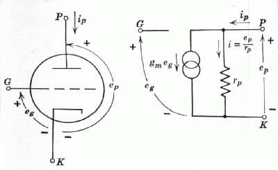

Equation 7.21 may be represented by either of two simple equivalent networks. These are shown in Fig. 7.6b and 7.6c. Figure 7.6b has as an active element an ideal current generator gm eg (infinite parallel internal impedance) and Fig. 7.6c has as an active element an ideal voltage generator u eg (zero series internal impedance). Note that in each case the output of the active element is proportional to the a-c grid-cathode voltage eg.
Applying Kirchhoff's current law to Fig. 7.6b, ip may be written as the sum of the current gm eg through the generator and the current ep / rp through rp. Thus the network of Fig. 7.6b does indeed represent equation 7.21. Kirchhoff's voltage law applied to Fig. 7.6c states that the sum of the voltages around the plate circuit loop is zero.
ep - ip rp + u eg = 0 (7.22)
This is a simple rearrangement of 7.21.
We may conclude that the small signal a-c behavior of a circuit containing a triode may be analyzed by replacing the triode by either of the equivalent networks shown in Fig. 7.6. The same equivalent networks may be used for tetrodes and pentodes provided the screen and suppressor grids are held at constant potentials. Since and rp tend to be extremely high for tetrodes and pentodes, the current generator network is usually used for these tubes because it does not involve .
In a tube there are inter electrode capacitances between all pairs of electrodes, as suggested in section 6.6. The three inter electrode capacitances of a triode are represented in Fig. 7.7a and are included in the equivalent networks in Fig. 7.7b and c. The equivalent networks of Fig. 7.7 more completely represent the behavior of a triode than those of Fig. 7.6. The networks of Fig. 7.7 can be used , for example, to derive the expression for the input capacitance Cin of a triode (Miller effect) which we found earlier by physical arguments (see equation 6.47).
Fig. 7.7. Representations of a triode when inter electrode capacitances
are included.

- Equivalent network treatment of a simple triode amplifier
We now use the equivalent networks to reexamine the simple triode amplifier, previously discussed in section 6.5. In Fig. 7.8 the triode amplifier circuit is shown in (a), the ideal current-generator representation in (b), and the ideal voltage-generator representation in ( c). Note that in the equivalent circuit representations of the amplifier, the emfs of the batteries Ecc and Ebb are not indicated, since only a-c voltages and currents are considered. The internal resistances of these batteries are assume negligible, and are not shown. Inter electrode capacitances are ignored so that this analysis is only valid at low or moderate frequencies.
The gain K of the amplifier shown in Fig. 7.8a is given by the ratio of the a-c output voltage ep to the a-c input voltage eg. From Fig. 7.8b or c it can be seen by using Kirchhoff's laws to find ep in terms of eg that the voltage gain is
K = ep / eg = -RL / (rp + RL) = - gm rp RL / (rp + RL) (7.23)
In amplifiers employing tetrodes and pentodes, rp is normally large compared with RL. The gain is the given by
Kpentode -gm RL (7.24)
Equations 7.23 and 7.24 are seen to be the same as those found in the previous chapter by graphical means (equations 6.44, 6.45, and 6.49). The gain is negative, indicating that the polarity of the signal is reversed in going through an amplifier stage.
Fig. 7.8. Triode amplifier and equivalent networks
