An n1ir niche Antenna for restricted spacesDownload the "H Flyer" EZNEC file Now! This is a wonderful and useful addition to the radiating structures family. Of the many applications that can be anticipated, one example is the frustrating situation of being an apartment/operator. This design just loves loss - in fact it is optimized with loss. Point its beak into the nearest potted plant and your F/B will SOAR! Shag carpet just doesn't cut the rug as ground? Apply a slightly saline mist while operating, or simply lay, or have a friend lay beneath the antenna (be sure to wear sun-screen). |
The Following design fits within a box with a volume of 0.122 by 0.196 by 0.210 wavelength The lowest portion is not even one inch above ground. Unfortunately this height is very necessary for the desired characteristic of optimized Front To Back ratio AND match. In the data displayed below is the consequence of lifting this design only 11 more inches. The consequence of this proximity of earth is felt as an "optimization" of F/B, but it also felt in the efficiency which "deafens" this antenna. 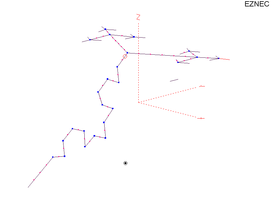 |
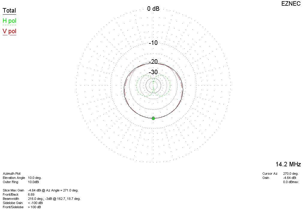
This view is with the favored radiation lobe overlayed.  The view below is with a comparison design, the "H Flyer." This design demonstrates how the usefulness of a fractal design is quite low offering only a fraction of a dB difference, worst matching, and nothing really gained by the complexity of implementation. 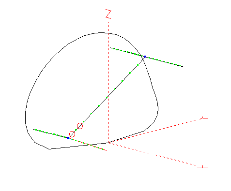 Outer Scale = 10 dBi When we look at the data cold, the best signal out is nearly -1 dBi. The gain at 10 degrees elevation is 4 dB below this. When we compare it to the "H Flyer" to the right, we can see there is very little difference between the two (a fraction of a dB). 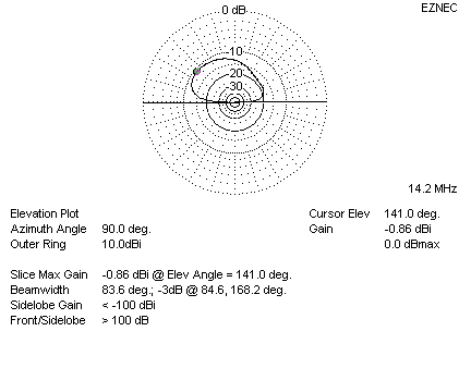 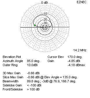 |
|
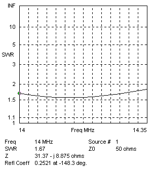
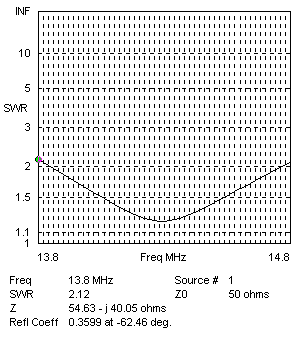
SWR Across the band is slightly better than reported elsewhere. When compared to the "H Flyer" to the right, we observe that the "H Flyer" has considerably more matching range than the fractal. IMPORTANT NOTICE TO CONSTRUCTORS:
|
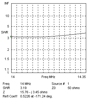
SWR Across the band is quite upset for what is otherwise a modest shift of less than a foot in elevation change 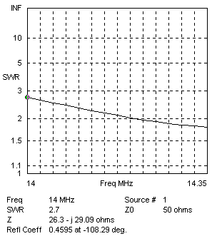 |
|
With a perfect ground we find the native value of the structure is at best a 16 Ohm load. IMPORTANT NOTICE TO CONSTRUCTORS:
|
|
Outer Scale = 10 dBi The DX angle identified as being 10 degrees here reveal the characteristic F/B and Deafness. The two go together in this design. If you wanted to, say, "get the wax out of your ears!" by raising this away from earth's deadly embrace; then yes, hearing will improve. However, the distinctive F/B will dissappear. And you will lose match.... IMPORTANT NOTICE TO CONSTRUCTORS:
|
