Triadic Koch Curve
Two antenna forms based on the Triadic Koch Curve will be analyzed. The first a mono/dipole form and the second
a loop form. The  object of this
study is to observe the resonant behavior of an antenna structure that is built up incrementally in sections of
four wires. These cyclic elements (much in the sense of array or yagi elements) have an unique shape that is a
fundamental pattern for the entire structure. For the Triadic Koch Curve, these 4 wires give the appearance of
a triangular jog in a vertical line. object of this
study is to observe the resonant behavior of an antenna structure that is built up incrementally in sections of
four wires. These cyclic elements (much in the sense of array or yagi elements) have an unique shape that is a
fundamental pattern for the entire structure. For the Triadic Koch Curve, these 4 wires give the appearance of
a triangular jog in a vertical line.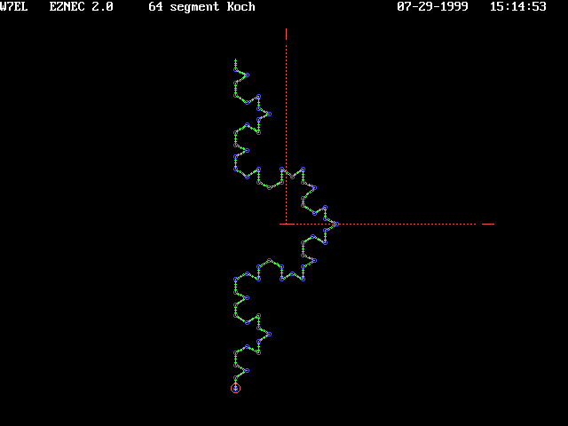 The
antenna shown consists of 64 straight wires, each 1.1 meter long; total height is 30 meters. This antenna lies
entirely within the YZ plane. The basic curve of the greater structure can be found in the first four wires' shape
(cyclic element shown in small inset). The
antenna shown consists of 64 straight wires, each 1.1 meter long; total height is 30 meters. This antenna lies
entirely within the YZ plane. The basic curve of the greater structure can be found in the first four wires' shape
(cyclic element shown in small inset).SWR frequency sweeps were performed on the structure each time a cyclic element was added. The number of resonances were noted and then another cyclic element added. For the structure shown here, there are 16 cyclic elements. In the study of SWR for element 1, there was only 1 resonance between 5 and 50 MHz. When cyclic element 2 (wires 4 through 8) was added, the number of resonances between 5 and 50 MHz increased to 3. With the addition of each additional cyclic element, additional resonances were added to the structure. |
Fractal ResonancesMore kinks means more resonances, especially for the Triadic Koch. Through the progressions of constructing this final form, each iteration presented more resonances to a constant frequency sweep of the structure.
|
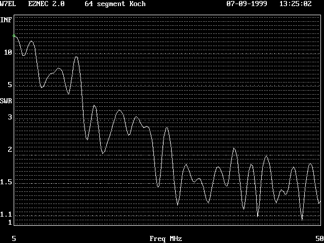 Same data
viewed from a Hi Z perspective of 200 Ohms Same data
viewed from a Hi Z perspective of 200 Ohms |
Folded Koch Curve to present a LoopHere, the curve from above is folded back on itself and fed at the sharp apex in the lower left corner (the
junction of wire 1 and wire 64). There are no shorts in the structure as might be suggested by the proximity of
points illustrated below. The first difference between this form and the standard form is found in the lower count
of resonances for constant wire length. One such site I evaluated is in the pinch that just precedes the ballooning of the structure (wire 8 end 2 to
wire 57 end 1). The intent was to see if the minor loop developed to the left of the drive would serve as a shunting
stub to the major loop to the right. |
Wire 1/64 Fed (as shown above)
|
Wire 15 Fed (broad apex with wide symmetry)
|
Shunt Fed
This too exhibits the pairing of resonances such as the sixth and seventh nulls in this display. The Object of this study, to observe tuned shunts, is lost in the resonances as it is. It would be tempting to embrace the twining of resonances at nulls 6 and 7, but these twinnings are too common otherwise. |
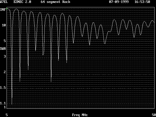 This SWR
chart is for the aggregate of 14 cyclic elements. Mentioned earlier was that for 2 cyclic elements there are 3
resonances. Here for 14 cyclic elements there are something like 18 resonances.
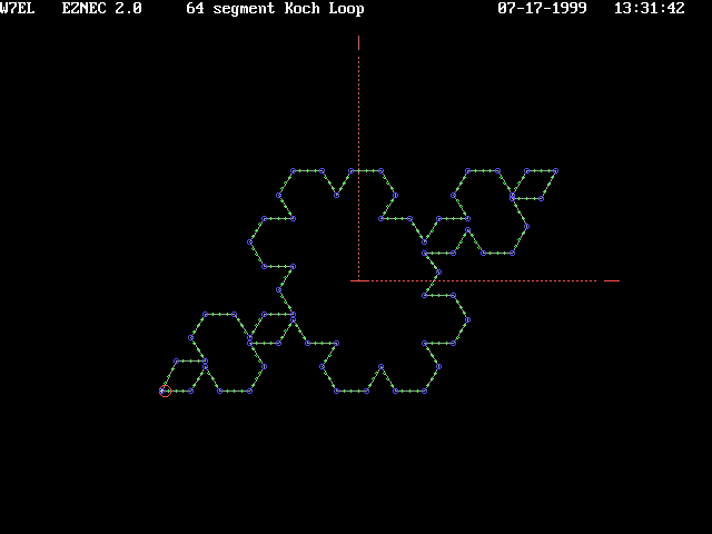 The
structure's symmetry lends it self to a number of possible drive points. The first is already described and shown.
Another possible site moves the source to the right lower corner, the broad apex. There are also a number of closely
paired but mirrored oppositions in the design that could serve as drive points. They lie along the diagonal line
extending from the lower left corner to the upper right corner.
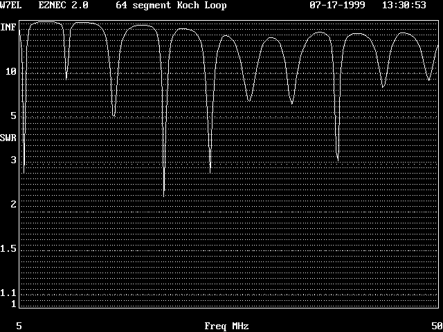 Note
how the number of resonances has dropped by roughly half. That is, it exhibits the number of resonances as found
in an 8 element monopole. More notable are the following variations in drive that reduce the number of resonances
further.
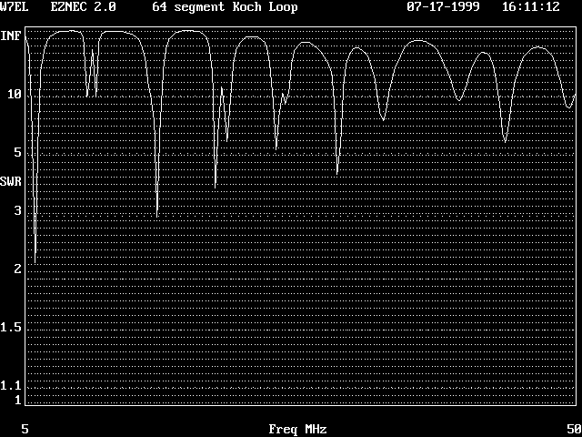 This feed seems to exhibit a boundary condition. In other data not shown here are similar displays
of nulls paired closely in frequency and certainly not harmonically related. The fourth, fifth, and possible sixth
nulls show closely paired resonances.
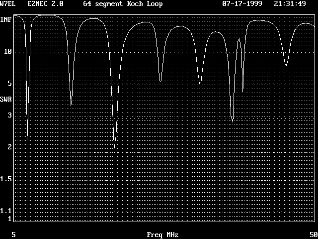 This is an opportunistic feed of the structure found at the pinching of the loop at its closest points.
The antenna was fed as two loops in parallel electrically but in series geometrically (W8E2 to W57E1). This method
of feed presents roughly the same number of resonances as found in a monopole fractal of 6 cyclic elements.