2n2-40 Manhattan Style Project
It all started innocently enough. I had recently completed the MH101 SW30+ rig, built manhattan style and was looking for another project. I had wanted to build the 2n2-40 by Jim Kortge, K8IQY for some time. Jim was one of the Elmers on the MH101 course. I made an announcement on QRP-L that I intended to build the 2n2-40 and was wondering if anyone wanted to build along. At first I got about 10 replies and kept everyones email address in my email address book. But the replies started to POUR in! It was quite apparent there were a lot of people who wanted to build this radio.

Fast forward a couple of weeks. I started a mailing list using Yahoo Groups. Here is a link to our site; http://groups.yahoo.com/group/2n2-40/. It is possible to join the list without being a member of Yahoo, but it's probably better if you join Yahoo (it's free) to get all the new schematics and the ability to search the message archives.

Here is a link to Jim's homepage, it contains everything you need to get started; K8IQY

This link will take you to extreme closeups of the radio. I will probably add some annotations to these images in the near future.

Back to my QSL.net homepage

The build...

10/15/2001 - Rx/Tx Driver
rxtx1.jpg - The RX/TX driver circuit and board overview. You can see that I've marked up the board with pencil to match the suggested layout from Jim's webiste.

rxtx2.jpg - The RX/TX driver circuit

rxtx3.jpg - The RX/TX driver circuit - different angle.

Soapbox
I tested the circuit and it seems to work as advertised. [more later]

Having fun so far. I just received the rest of my parts in the mail, so it should nothing but fun from here on out!

10/17/2001 - Starting the VFO
vfo-start-image-004.jpg - Glued down a few pads and started with the T50-7 wound with 44 turns of wire.

vfo-start-image-002.jpg - I think I'm about 1/3 of the way through the VFO at this point. You can see the Rx/Tx driver in the background.

vfo-start-image-003.jpg - Here is a close up of the previous image.

vfo-start-image-001.jpg - Slightly better image quality here. The MVAM109 is in front and just to the right is the optional 3pf-10pf trimmer cap.

vfo-start-image-005.jpg - A different angle; here you can see C12a and C12b (different designators on the new schematics) and the main trimmer cap (it has some green on it).

Soapbox
Not much to say - just having a blast building this radio! I hope to finish the VFO tonight and test it by listening for it on my receiver.

10/19/2001 - VFO Finished
Got the VFO finished last night but ran into some problems. More on that in the Soapbox.

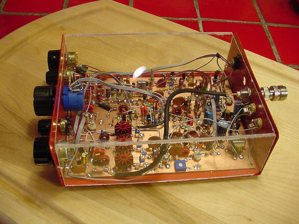
vfo-finished-006.jpg - Overview of the VFO with the 10-turn pot wired in.

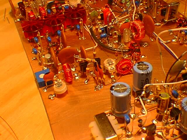
vfo-finished-007.jpg - Close up, looking up at the trimmer caps, the MVAM109 and the partially hidden by C4 T50-7 (L1).

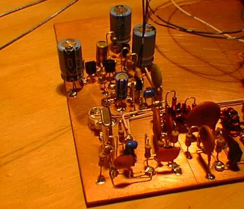
vfo-finished-008.jpg - Slightly different angle, shows T5 and Q2 and Q3.

vfo-finished-009.jpg - Another overview from a different angle.

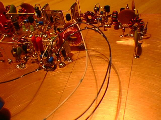
vfo-finished-010.jpg - Nice shot showing L1.

vfo-finished-017.jpg - Now we get to the questions; Here is an O'scope shot of the output of the secondary of T5 with POT1 turned fully counter-clockwise. Volts/Div is 50mV and the probe is a 10x attenuator, so each hash mark is 500mV, or half a volt. The amplitude peak-to-peak is about 1.5v with POT1 at this setting.

vfo-finished-019.jpg - Here is an O'scope shot of the output of the secondary of T5 with POT1 turned fully clockwise. Volts/Div is still set at 50mV. The amplitude peak-to-peak is about 2.5v with POT1 at this setting.

The question is; is this OK?

By the way, the frequency is calculated as follows; The Time/Div setting is .1uS, or .0000001 of a second per hash mark on the X axis.

In the first image, the period is approximately 4.79 x .1uS, or 4.79 x .0000001. Frequency is the reciprocal of the period, so 1/ 4.79x.0000001, which equals 2.088Mhz. Sure enough, placing the rig next to a receiver shows the VFO oscillating at 2.085 (I did fiddle TC4 prior to this however).

The second o'scope image shows a period of about 4.6uS - I'll leave the frequency calculation as an excercise for the reader (always wanted to say that!).

Soapbox
Problem:
There is a conspiracy among potentiometer vendors to frustrate me in perpetuity. I initially wired POT1 incorrectly and had an almost working VFO for quite sometime. Only problem was, when I would get near the end of the tuning range, it would go backwards (fast). After finding the correct pinout of POT1, the VFO worked.

The range of this VFO is from 2.085MHz to about 2.170MHz - I think this OK, but I'm waiting to hear from the rest of the crew about it.

I also have the peak-to-peak situation outlined above. I'll report back here when it's sorted out.

10/25/2001 - Answers to questions
The answer to widening the VFO was to replace TC3 (a 3-10pf trimmer) with a 22pf NPO cap.

The voltage peaking described above was caused by too little capacitance on C12 which caused T5 to not come into tune until nearing the top of the frequency span. I Increased the capacitance of C12 by adding a 33pf NPO cap in parallel. The unloaded output of the secondary of T5 is now 3v p2p at the bottom of the range, peaking at 5v p2p at the middle of the range and 3v p2p at the top end. I soldered in a 100 ohm resistor at the output of the secondary of T5 to act as a load - there is very little variation in output in this configuration.

10/26/2001 - DB Mixer
I'm building the 12db fixed gain version of the DBM and doing the layout by hand.

dbm-start.jpg - This T4 and the 4 1N4148's. I like the look of this configuration! Sorry for the poor focus.

dbm-midway.jpg - This T4, the 4 1N4148's, T3, C15 and T6. T6 was a little tricky (like the trifilar's weren't?). I wound T6 as follows. 4 turns, then leave a large loop between turn 4 and 5 - this is the "tap." An additional 11 turns are then wound after the tap. The one turn secondary is simply a wire passed through the middle of the toroid and mounted on pads on each side. I mounted C15 on its side from the pad that pin 1 of T3 connects to and then connected the tap of T6 to the other side. It looks a little funky, but it should work.

Well, I ended up changing the aforementioned layout a little...

dbm-001.jpg Here is the new layout. T6 is now sideways with 4 pads in front of it. In this picture you can see the LED, which does in fact turn on when the rig is powered up (cool!).

dbm-002.jpg A different angle showing the VFO with the wire running to the DBM.

dbm-004.jpg DBM a little farther along...

dbm-006.jpg Testing the VFO and DBM (more in the Soapbox).

dbm-007.jpg Nice shot of the complete DBM.

dbm-008.jpg And another.

dbm-009.jpg Same same...

dbm-010.jpg Overview of the board so far.
Soapbox
OK, where to start...

Well, it works! I had a false start with the placement of T6, but after drawing out the layout a few times I decided I wanted it sideways, with all four pads in front of it. After that, things came together pretty well. You can see a few wires in the pictures, those are for the VCC and for testing and will be cleaned up later.

Testing the DBM (and VFO for that matter) calls for feeding a receiver tuned to 4.915Mhz from the output of the DBM (pins 4/5 of T4). A ran a wire (not coax which is what's supposed to be used) to my trusty Radio Shack DX-398's antenna. You then run an antenna to the input to the RF input filter (pin 1 of T1).

With the VFO set to 2.135Mhz (oh yeah, I set that up first), you transmit from another rig into a dummy load on 7.050Mhz and you should hear it on the 2n2-40.

Nothing.

I tuned around a bit with the VFO, still nothing but noise.

I then remembered an email in which Jim said "Yes again. If the amplifier oscillates like mad, that's a sure sign that the one turn lead is phase incorrectly. With it phased correctly, the amplifier is very stable." (he was talking about T6)

So, back to the bench. I switched the "one turn" secondary of T6 and hooked the radio back up to the test circuit (if you will).

Bingo! It worked! I had to tune the reciever down about 500Hz, but it does work! I then peaked TC1 and TC2 and started tuning around with the VFO. Sure enough, I could hear CW! This is FUN!!!

Hopefully will have some time this weekend to continue on.

10/28/2001 - Mixer Amp/IF Filter

if-001.jpg - Here is the start of the Mixer amp coming of point "C" of the DBM. Shown are L5, C24, D13, R21 and Q5.

if-004.jpg - The mixer amp up to R38. About to build the Variable Xtal filter.

if-005.jpg - Here the start of the filter. Y2 and D9 are soldered into place and I'm about to head "up" the circuit towards the two LED's (D14 and D15).

if-007.jpg - Here you can see D14 and D15 soldered in place. I really like the fact that Jim used LED's!

if-008.jpg - The filter is now complete and I'm working on the layout for the IF Amp. Here you see all of the xtals up to Y4 in place.

if-009.jpg - This is my favorite picture to date! The lighting is a little off, but the effect is great. The shadows give some perspective of height and the board reflects the light and really shows its copper tone.
Soapbox
Doing this layout entirely by hand as well. I felt a bit cramped building the DB Mixer, so I'm going to try turning things around a little here. One thing I've learned is don't try to follow the direction of the schematic directly. Turn it upside down and sideways and build in the direction that makes sense. I'm finding that by looking at it from different angles (even inversly), different layouts are emerging.

11/1/2001 - IF Amp, Product Detector and Rx Local Oscillator
filter-etc-004.jpg - This is the start of the IF Amp. Here we see Q6 on out to R24 (laying flat).

filter-etc-012.jpg - This is the finished IF Amp. Here we see T8 and Q7 as well as T9 waiting to get soldered in.

filter-etc-013.jpg - Same shot only zoomed out a little showing more of the radio.

filter-etc-014.jpg - Here we see the Product Detector from the end of the board.

filter-etc-015.jpg - Here we see the Product Detector from the top of the board. Also shows the VFO, IF Amp and Filter. About to start on the Rx/Lo. You can see where I made a soldering mistake and tried to clean off the board. You won't notice it as the radio ages and the copper dulls a little (I know this from experience ;) ).

filter-etc-017.jpg - This is the finished Rx/Lo shot from the top of the board.

filter-etc-018.jpg - This is the finished Rx/Lo shot from the bottom of the board.

filter-etc-019.jpg - Nice pic of the filter through the Rx/Lo.

filter-etc-020.jpg - Nice pic of the filter through the Rx/Lo - different angle.

filter-etc-021.jpg - Nice pic of the filter through the Rx/Lo - different angle.

filter-etc-022.jpg - Trying to duplicate the lighting of a previous image... check it out.

filter-etc-025.jpg - Sort of a side-on view of the recv strip.

filter-etc-026.jpg - This is an overhead shot of the board so far. The Rx Mute and Audio Amp will be built on the left side going up.

Soapbox
Fairly ambitous couple of nights! I've changed my layout technique somewhat by building directly off the schematic instead of drawing it out on paper first.

Hope to have the Rx Mute and Audio Amp done this evening so I can listen to the 40m QRP-L fox hunt on my 2n2-40!!!

11/2/2001 - Rx Mute and Audio
audio-001.jpg - The Rx Mute is done here. I foolishly thought Pot 3 was a 10K trimmer and soldered one in... it's been replaced with the on/off switch/10K pot that bought for this purpose.

audio-002.jpg - This picture is here because it shows what happens when you get excited and build something in a hurry. Here you see Y1 and TC5. Missing from the picture is L3, the 39uH inductor that goes in between them. It was eventually added.

audio-005.jpg - Here you see a good chunk of the audio amp completed. The picture is underlit, unfortunately. I really like the look of the 470uF electrolytics!

audio-007.jpg - Here is a nice shot looking up at the completed Audio Amp.

Please note: This Amp doesn't work as its shown here. I fuddled up some connections and had to troubleshoot it - more on that below.

audio-008.jpg - Here you see the real Pot 3. Note that L3 hasn't made it into the picture yet.

audio-012.jpg - Ahhhh, L3 seems to have appeared now.

Soapbox
Um, well, hmmm... I was hoping to power up, hook up to an antenna and have signals come pouring out the speaker. That didn't happen.

After troubleshooting, adding L3, moving the connections on Q9, Q10, Q11 and Q12 to where they should be, I finally had sounds! It's a bit quiet though. There really isn't much noise and that sort of concerned me. Numerous people have posted and said that the recv on this radio is in fact very quiet. I'll going to fiddle with it a bit more this evening.

11/04/2001
Problem solved.

audio-working.jpg - Here is a shot of the rig in its working state

Here is the text of the message I sent to the 2n2-40 group;

OK, the key to using the circuit from Joe's Quicky #1 is to build
correctly so the signal you're looking at is the one coming from the
oscillator and not somewhere else. After this important step has been
done...

Inject the signal into the input of your amp. Go to the other end of the
amp and see that it's been amplified (didn't bother to measure, it's a
lot).

So, the audio amp was OK.

I decided to inject an RF signal from my heath RF Generator and follow
it through the rig (should have done this a few days ago, but...). It
seemed to get lost just after the RF amp. Hmmm... rechecked everything,
parts in correct place, correct parts... turned out it was a bad solder
joint on Q4, 'cause after reheating it (and a few others), I've got big
audio!

Probably helps that it's a contest weekend too 'eh? But no kidding,
there is enough volume on that thing to fill the room.

Yeeeeehah!

Off to build the xmiter next week and hopefully get it on the air!

73 de John, N1QO

John Wagner wrote:
> 
> Gang,
> 
> I have triple checked (and then some) my rig and can't figure out why I
> have low audio volume. I tried a different speaker, checked all the
> 2n2222's voltages, everything seems to be correct.
> 
> I built Joe's Quicky #1 http://www.njqrp.org/quickies/quickie1.html
> thinking it might be useful, but I'm not sure what I'm doing with it. I
> tried injecting the signal into the audio amp and followed it through -
> again, not sure what I'm looking for here.
> 
> Any suggestions appreciated.
> 
> 73 de John, N1QO

11/4/2001 - Tx Finals and Output filter
txout-final-004.jpg - This is the space where the LPF, Finals and RF Driver will go.

txout-final-007.jpg - This is the space where the Coscode Amp, Single Balanced Mixer and Tx Oscillator will be built.

txout-final-010.jpg - Here you can see the LPF has been built and the two strips for the finals are glued into place.

txout-final-013.jpg - The final transistors are mounted. Also shows one of the heat sinks sitting next to them.

txout-final-014.jpg - Another view of the "naked" finals.

txout-final-016.jpg - Building out towards the Tx driver you can see R57, R58, R59 and C58. C59 and C60.

Soapbox
I decided to go out of step here because I really wanted to see what the radio would look like with the finals mounted. The first picture of the next serious shows the finals with their heat sinks - awesome!!!

11/6/2001 - Cascode RF Amp, SB Mixer and Tx Local Oscillator
cascode-001.jpg - With the RF Amp finished, this picture shows the first pad of the Tx Cascode RF Amp. It also shows the finals with the heat sinks.

cascode-003.jpg - Here you can clearly see POT 4 and T13. I make a serious mistake just after this which doesn't show up in the pictures well. It showed up when I tried to key the radio though. More on that in the Soapbox.

cascode-005.jpg - Just about to the Tx SB Mixer, here you can see TC7.

cascode-008.jpg - Here we see T12 and T11.

cascode-009.jpg - Another view of the same.

cascode-009.jpg - And yet another...

working-013.jpg - Quite a leap, but I wanted to show a picture of the radio working. I'll take some pictures of the TX/Lo when I get a chance. Right now I'm working in a case for the radio. It's gonna be awesome... and RED!

incase.jpg - Nice BIG picture of complete radio with it's clear top case.

Soapbox
So yeah, it works!!! It wasn't easy though. I made a mistake wiring up the Tx Cascode RF amp and then many more mistakes trying to figure out what the problem was. What I did was wire in Tx power directly into the base of Q16. I ended up frying a bunch of parts with slips of the o'scope probe and other manuevers.

But the radio does work!

In fact, I worked my first DX on 40m EVER with this radio! I've been messing around trying to do some mods to the RF Mute circuit. One time I hooked the radio up and and I heard K1RX signing with UT5MD. I thought there was no way I could a UT5 on 40m, but there he was. I knew there was no way I could work him with my 2.5w radio, but when he signed with K1RX I called him. He came back to me and gave me a 579 RST!!! Yep, Vlad in Kremenchuk Ukraine! Unreal. When I told the group about it, Jim said he had forgot to mention that 2n2-40's have their own special brand of Mojo! Pure magic in my eyes!

"Do not be afraid of standing up in front of everybody and failing miserably. People before you have failed and people after you will fail. If you don't fail at something, you aren't trying hard enough and you aren't going to grow. Failure is not an option, but it is a very real possibility. The key to not failing is to look at others who have failed before you and don't repeat their mistakes."