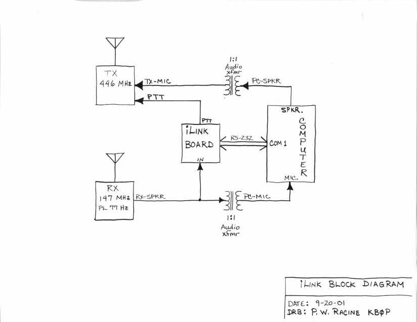
The following is a layout of my repeater system and what was needed to get it on the air.
The ILink system was designed by Graeme, M0CSH, and I take no credit for its success.
The circuit below is only required by repeater
control stations (sysops) and not by the average PC user of ILink. This information is only
provided to help other amateurs link their repeater to the ILink system.
The link receiver consists of a separate Hamtronics R301 VHF receiver with the Hamtronics TD-5 subaudible tone decoder. The VHF receiver is tuned to 147.240 MHz and receives the repeater activity off-air. Whenever there is activity on the 147.240 repeater COR, the repeater generates a 77 Hz subaudible tone which in turn un-mutes my link receiver.
The link transmitter consists of a separate hamtronics T304 UHF transmitter which sends link audio
to the repeater via a UHF link. Whenever the link COR is active at the repeater, the 77 Hz subaudible
tone is disabled to prevent a feedback loop into my link system. The UHF link is voted at the repeater
and its priority is set very low. This allows any 2 meter activity to override the link which in turn
gives us full control of the link system.
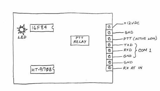
This is the layout of my iLink board. When building this board, I used screw terminals for
all of my external connections. I find this dresses up the board nicely, and makes it very
convenient when testing the circuit out; there is no need to solder and unsolder connections.
The circuit is build on perf board which was purchased from Radio Shack. A lot of my
projects are down with perf board due to the time saved in laying out a board. Also, perf
board is easy to work with if there is a time when I need to make a modification to the circuit.
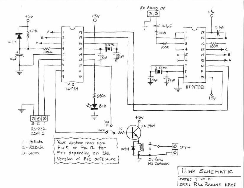
The ILink circuit was designed by Graeme, M0CSH. I drew up a schematic based on the original schematic obtained from Graeme, himself. As you can see, the ILink circuit consists of 2 main components, the EPROM and the DTMF Decoder IC's. Aside from these two components, which must be specially ordered, the remainder of the components are supplied by your neighborhood Radio Shack store.
The largest hurdle to over come when building the ILink board is trying to figure out how
to program the EPROM (PIC). If you decided to build your own system, one of the tools you should
purchase is a PIC programmer which could cost you about $65.00. You also have the
option to build your own PIC programmer, which still adds some aditional cost to the original project.
The other option is to order the pre-programmed PIC from Graeme, M0CSH. You will find more
information on this at his website, AACNET MANAGEMENT.
I put together a parts list and supplier for all the part which you will need to build your own
ILink circuit. Again, this circuit is only required by repeater control stations (sysops) and not
by the average PC user of ILink.
ILink Circuit Parts List
1 -- PIC 16F84 IC -- Digikey, p/n PIC16F84-04/P
1 -- DTMF Decoder IC -- Holmate, p/n HT9170B
1 -- 2N4401 NPN transistor -- RS, p/n 276-2058
2 -- diodes -- RS, p/n 276-1122
1 -- 4 MHZ Ceramic Resonator -- Digikey, p/n X902-ND
1 -- 3.58 MHz Ceramic Resonator -- Digikey, p/n X901-ND
1 -- 100 Ohm resistor -- RS, p/n 271-1311
1 -- 680 Ohm resistor -- RS, p/n 271-1117
1 -- 1k Ohm resistor -- RS, p/n 271-1321
1 -- 4.7K resistor -- RS, p/n 271-1330
3 -- 100K Ohm resistor -- RS, p/n 271-1347
2 -- 0.1uF capacitors -- RS, p/n 272-135
1 -- 10uF capacitor -- RS, p/n 272-1025
1 -- 5 Volt Relay -- RS, p/n 275-240
1 -- Red LED -- RS, p/n 276-041
1 -- PKG of Terminals -- RS, p/n 276-1388
1 -- 5 Volt Regulator -- RS, p/n 276-1770
Misc. Parts -- Chip Sockets, Project Box, Stand Offs, Jacks
 Return to Willy's Wonderful World