
During the Winter of 2015, Yaesu's WONDERFUL promotion to distribute the DR-1X Fusion repeater with an offer that could not be ignored,
I believe could lead to an increase in popularity of the FUSION (C4FM) digital mode on 2 Meters and 70 CM. I travel a lot for my job, and I have
connected with amateur radio operators throughout many cities in the USA and every place I have visited has at least one club that plans to
replace some of their repeaters with a Yaesu DR-1X machine. I am excited to watch and see what becomes of all of this.
The U.P. (Upper Peninsula of Michigan) currently has no other digital FM repeaters in operation during this writing (April 14, 2015).
However, many U.P. Amateur Radio clubs have signed up for and purchased the Yaesu DR-1X repeater. Soon, C4FM will be the digital mode
of choice for the U.P.
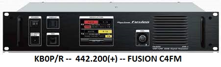
I received our Yaesu DR-1X in March 2015, and the FIRST C4FM repeater in the U.P. went on the air on March 14, 2015! As far as I am aware,
based on my correspondence with other U.P. clubs during my travels, the KB0P/R repeater is the FIRST digital FM repeater to go operational
in the U.P. of Michigan. This repeater is located in Ishpeming, Michigan; operating on 442.200(+) MHz; mode of operation is C4FM/FDMA. To access
the KB0P/R repeater, one needs to use a Yaesu radio capable of C4FM (the FT1D handheld, the FTM400DR mobile, or the FT-991 base tranceiver).
(Q1) Can I cross-band my FT-8800 (base station) between 2 Meters and 70 CM, and then transmit with my Yaesu FT1D handheld using C4FM, to extend the range of my HT in order to work a distant FUSION C4FM repeater?
ANSWER: No. What I mean by this is, "no, it does not work". I tried this without success. The FUSION repeater receives the signal from
the FT-8800 as a analog signal and does not trigger the C4FM mode. Also, due to the limited audio bandwidth of the FT-8800 used in this manner, the
full bandwidth of the C4FM is not completely passed through.
(Q2) Can I connect IRLP/Echolink to the 15-pin accessory port on the rear of the DR-1X, and will it work?
ANSWER: Yes and No. It worked. At first I had to work out some keying issues (I will address these issues, below) and there are still other minor
issues with the PTT. It works in one instance, but did not work in another instance, and I will show how I did it, below.
(Q3) When using FM (analog) or C4FM (digital), the audio that is exported out the 15-pin accessory jack on the rear of the DR-1X, is it analog or digital? Analog audio is required at the 15-pin accessory jack if the DR-1X repeater is installed on an existing analog FM linked repeater system.
ANSWER: Yes, I learned by experimenting that analog and digital audio is available on the 15-pin accessory jack.
(PIN 8) Discriminator is accessed on this pin. When a digital station is received by the DR-1X receiver, the output of PIN8 will be digital audio. When a analog station is received by the DR-1X receiver, the output of PIN8 will be analog audio (pre-emphasized).
(PIN 9) This pin provides analog audio (de-emphasized). Regular "human being" audio is present at this pin no matter if the user is transmitting FM (analog)
or C4FM (digital).
(Q4) I purchased a Yaesu HRI-200 Wires-X box (why? I don't know?). Now that I own the thing and have it registered, I must figure out how to work it. The Wire-X box connects to the DR-1X through the 10-pin (round S-Video-looking plug) accessory jack on the rear of the repeater. I turned it on once and played with it and then gave up and went to shovel snow, instead (frustrated). My question is Can I connect the HRI-200 to the 10-pin jack, and connect a repeater controller (IRLP) to the 15-pin jack and allow inter-connectivity? I tried this briefly (prior to going out to shovel snow) and I think it worked. First, I must figure out how to work Wires-X!
ANSWER: Still to be determined.
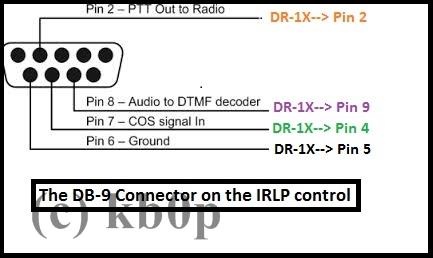
 IRLP/ EchoLink Wiring Connection (with no external repeater controller):
The first remote wiring connection I made to the DR-1X repeater was to interface my IRLP/Echolink system to the repeater utilizing the 15-Pin accessory jack on the rear
panel of the DR-1X. This connection worked well, but I did experience a couple issues. I will address these issues, below, under the ISSUES heading:
![]()
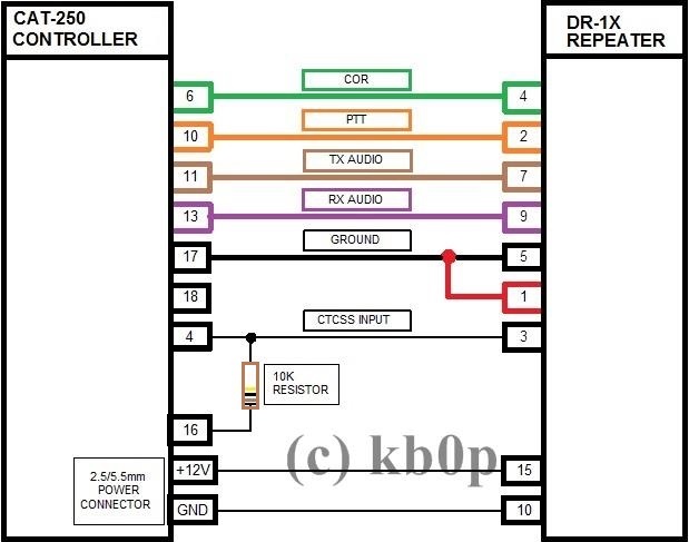
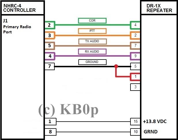
Remote Controller Wiring:Chances are, the DR-1X will be installed at a repeater site as a direct replacement for older equipment, requiring the use of an external repeater controller.
Since I own CAT Repeater Controllers, this diagram is used as an example on how to wire the DR-1X repeater to the CAT-250 controller. An important point is that with this
configuration, I am NOT able to use AUTOMATIC MODE (AMS) on the DR-1X repeater; this diagram is for ANALOG use of the DR-1x, only. Below, I show the wiring diagram
used at my repeater site to connect an external repeater controller to the DR-1X repeater. All PIN references are made to the DR-1X, 15-PIN accessory jack on the rear of the DR-1X.
On The DR-1X Accessory Jack
PL Tone on CORWith the onset of repeater linking and IRLP and EchoLink, being able to produce a PL tone on COR (or COS) is necessary; this is required to remotely control the remote devices (remote repeater or IRLP or Echolink system). Essentially, it is required that the repeater transmits (encodes) a PL tone ONLY when the repeater receiver squelch is open (when the repeater is receiving a signal). When no signal is received (for instance, when the repeater transmits to send an ID), no PL tone is transmitted.
I've been asked to help setup the Fusion DR-1X repeater to produce "PL on COR", to allow remote connections to linked-repeaters and IRLP or Echlink computers. Can it be done? YES. I did some experimenting and I will share with you what works and what does not work. To produce "PL on COR", it is required to use an external PL Board (such as the Communication Specalists SS-64 or TS-64).
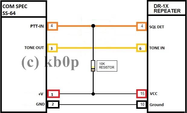
This is a wiring diagram of how to interface the TONE BOARD with the DR-1X to produce the "PL on COR" needed for repeater linking and IRLP/ Echolink systems. In my example, I am using the
DR-1X as a repeater (the internal controller), in ANALOG mode (fixed mode), and a Com.Spec. SS-64 tone board. Whenever a signal is received by the repeater, the tone board is turned on and
a PL tone is transmitted over the air.
An attempt was made to use the REMOTE I/O (PINS 11, 12, 13, 14), combined with the COR (PIN 4), in order to untilize the internal PL Encoder in the DR-1X, to produce a PL-ON-COR, without
the need for an external PL board. This did not work. Yes, the PL Encoder built into the DR-1X can be turned on and off using the REMOTE I/O logic, but.....once the PL Encoder was latched, it would NOT reset
until after the repeater transmitter dropped out of transmit. In other words, in theory a great idea, but in reality it did not work. The use of an external PL Encoder is required to
achieve PL-ON-COR.
There may be some confusion when it comes to REMOTE operation of the DR-1X repeater. In the menu of the DR-1X, there is a REMOTE function that can be enabled or disabled (page 25 in the manual). Then, there is the grounding of PIN 1 on the 15-Pin accessory jack, which activates REMOTE MODE. The two modes are different and pointed out, here:
(1) The Receiver Audio: The wiring of the IRLP board to the DR-1X involved 5 connections: Ground, PTT, COS, Audio in, and Audio out. During the initial test, I used DR-1X "Pin 8" as my audio-out connection to send repeater-receiver audio into the IRLP board (for receive). DR-1X "Pin 8" is discriminator audio output of the repeater receiver. This audio is NOT de-emphasized (which may be what you would like, in your case). But, the major issue I discovered with "Pin 8" audio is that it represents exactly what the repeater receiver hears over-the-air. When the DR-1X repeater is used in FM (analog) mode, the audio at "Pin 8" is analog audio. However, when the transmitting station into the repeater is using C4FM (digital) mode to communicate, the audio at "Pin 8" is C4FM (9600 baud, digital, white noise audio). So, it was learned that DR-1X "Pin 9" must be used to send receiver audio to the IRLP computer. "Pin 9" audio is analog when the repeater user is FM and the audio is decoded analog when the repeater user is C4FM.
(2) The PTT Did Not Work: The repeater would not key up! WHAT! I was using the PTT (pin 2), why isn't it working? I even went into the menu of the DR-1X repeater and turned on the REMOTE MODE, and still nothing. It didn't take long to figure out a solution. I learned that DR-1X "Pin 1" must be pulled low (L) to allow the "Pin 2" PTT to work. In my setup, I did not want to leave the DR-1X in remote mode (only when IRLP/Echolink is keyed up), to allow the repeater to work normally (as a repeater) when IRLP is idle. I soldered "Pin 1" to "Pin 2" as a test. When IRLP keys up the PTT, it also activates REMOTE by pulling both "Pin 1" and "Pin 2" to ground. When the station on IRLP/Echolink is done transmitting, the two pins return to high (H) and the repeater returns to normal control. THIS WORKED!
(3) Auto Mode Does Not Work: When using external PTT (Pin 2) along with REMOTE MODE (Pin 1) --remember that I tied these two pins together-- When the repeater is placed in AUTO MODE, the external IRLP board will not PTT the repeater. However, when the repeater is selected to FIXED MODE (no matter FM or C4FM), the external IRLP board does PTT the repeater. I have a theory that this is due to a "logic race" issue, but I will investigate and report the results, here.
(4) Internal Controller Bypassed: Simply, when using the 15-Pin accessory jack to control the Yaesu DR-1X, I confirmed that the DR-1X internal controller
is bypassed. Therefore, the CW ID does not trigger, the squelch-tail does not work, and the TOT (time-out-timer) does not work. BE CAREFUL!
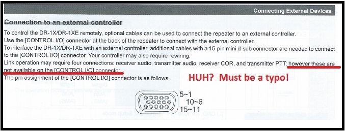
Refer to PAGE 17 in the DR-1X OPERATING MANUAL, and read the paragraph titled "Connection to an external controller". Do you see what I saw? When the paragraph is describing the pinout on the 15-PIN ACCESSORY JACK, it explains that in order to connect the DR-1X repeater to an external control, one must utilize the receiver audio, transmitter audio, receiver COR, and transmitter PTT, then the sentence goes on to mention that, oh, by the way, these points are NOT available on the CONTROL I/O (15-PIN JACK).....have a nice day. Say what?!
Let me assure you that these points ARE available on the 15-PIN ACCESSORY jack, and I am using them, today. Everything will be okay. But, I do have to admit,
I did panic at first until I tried it for myself, and then I sighed a breath of relief...whew!