|
(Click on an image for
a larger view) |
|
|
|
|
|
This Crystal Radio Set was started as my
eight and half year old son Zak's, third grade Science Fair project. |
|
|
|
|
|
The Crystal Radio Set was built from a 1920's Tapped
Coil design using a few scavanged parts and a hand wound coil on a PVC
pipe form. The only new parts were the germanium diode and the capacitor
shunted across the earphone. Though designed for reception of the
AM broadcast band, it can be easily changed for reception of
"shortwave" radio stations. |
|
|
|
|
|
On the first try, it worked pretty
well. We were able to tune about six or seven stations easily
using one side of my 80-meter Zepp ham radio antenna as the antenna and
my body as the ground. I plan to swap the 8-32 nuts on top of the
porcelain stand-offs used for the antenna and ground connections with
wing nuts so that they do not require pliers to tighten. |
|
|
|
|
|
Now I wished we would have used clips for
the component connections rather then soldering them because we
now want to experiment with the design and some of the component
values. |
|
|
|
|
|
The coil is 50 turns of #22 enamled wire
wound on a 3.5 inch diameter piece of PVC pipe about four inches long
and tapped every five turns. The variable capacitor is a dual
365-pf air type. (Only one of the dual variable capacitors
was used). Also used were a 1N34A type gemanium diode, a .001 uF
capacitor and an earphone. All of the components were
"hot-glued" to the wood base and then the electrical
connections soldered. |
|
|
|
|
|
|
|
|
|
|
|
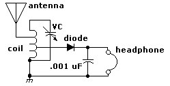
The schematic diagram for our crystal radio set |
|
|
|
|
|
|
|


