PROgramit - Construction
.
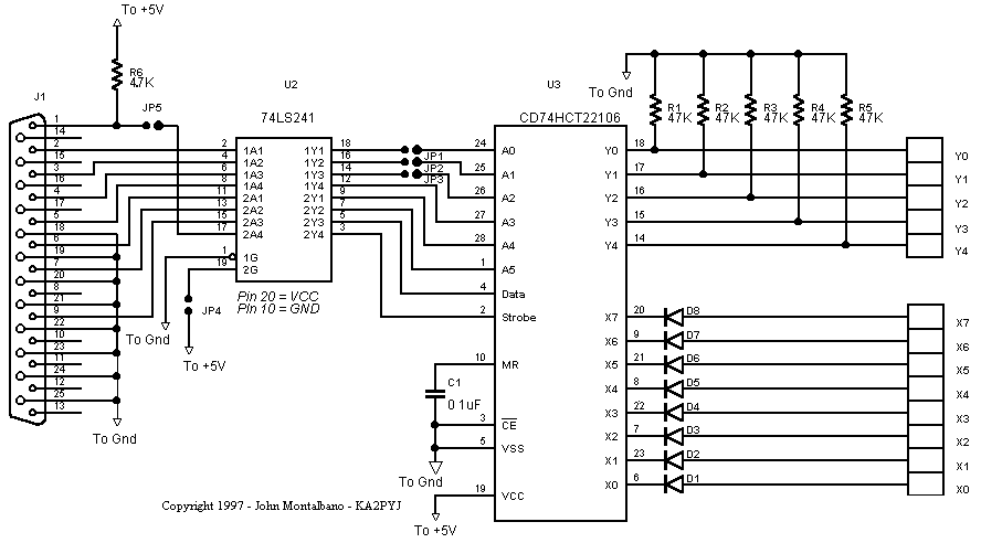
Figure 2. Schematic diagram of the parallel interface version
of the project.
The complete schematic for the parallel interface version
of the project is shown in Figure 2. The circuit can be built from thru-hole
components on a 2 - 5/8" X 3" piece of perfboard (Figure 3). I chose to
mount the DB-25 connector on the PC board and then cut a whole in the chassis
through which the connector is mounted . Be sure not to get any metal filings
onto the scanner's circuitry if you go this route. You could also sneak
a 25 conductor ribbon cable between the chassis and case to avoid cutting
this hole. The board requires 5 Volt power which was easily obtained from
the PRO-2032 power supply. In some scanners, a small battery powers some
of the 5 Volt power buses even when power is turned off. In that case you
will need to find a 5 Volt bus that is switched off completely, or connect
the optional on-board 5 Volt regulator to a switched source of 7.5 - 14
volts.

Figure 3 - The prototype was hard-wired using #30 gauge wire
on a 2-5/8" X 3" piece of perfboard.
The complete schematic for the serial port version is shown
in Figure 4. I recommend that you use a female RCA connector for the data
connection to the PC since you will be less likely to contact the center
conductor to ground when inserting or removing the plug with power applied.
 Figure 4 The complete schematic
for the serial port version of the interface
BACK


